
User's Manual

001-2019-500 Rev 0 Paragon4 – UHF, 700 & 800MHz User Manual
11
Although a rear-mounted fan brings in air from the back and blows it across the heatsink fins, a consider-
able amount of heat is generated during normal operation. The amplifier must have a minimum of 3 inch-
es of open space behind the rear fan to allow adequate ventilation. The air inlets and outlets should be
checked every 30 days and cleaned if necessary. If dust and dirt are allowed to accumulate, the cooling
efficiency will be diminished. Using either compressed air or a brush with soft bristles, loosen and re-
move accumulated dust and dirt from the air inlet panels.
Caution:
Do not operate this unit in a completely enclosed cabinet.
Crescend Terminal Block Torque Settings:
Although the manufacturer does not specify definite torque settings for its terminal block screws, the fol-
lowing values can be used:
• 8 In-lb (9 maximum).
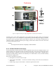
4.4.4 Paragon4 Power and Ground Connections
4.4.4.1 Power Connections
The Paragon4 base station’s modem-controller, radio (dual-RX & TX) and speaker panel modules receive
their +13.8VDC power via the backplane PCB. A 12AWG DC power cable provides power to the back-
plane PCB at the heavy duty power connector J20.
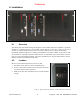
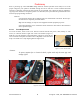
4.4.4.2 Ground Connections
The Paragon4 base station chassis requires a secure ground connection. A grounding 8-32 threaded
throughole pemstud fitted with a 8-32 screw, lockwasher and nut is provided on the bottom- rear of the
chassis, behind the speaker panel.
• Install a 3-4ft 10AWG grounding wire, crimped on both sides with terminal rings. Place one side over
the 8-32 screw on the non-exposed chassis side and firmly tighten with the lockwasher and nut.
• Place the other side on the rear side the power supply metal case, near the 25-pin connector. Use a ½
in 4-40 screw with lockwasher to secure the terminal ring to the metal case.
• If a –DC rail (0V) is installed as part of the system, the grounding lead may alternatively be fitted to
the rail terminal.
Caution:
Improper grounding between power supply case and rack frame may result in harmful voltage poten-
tials and/or miscellaneous power supply switching noise problems in both receivers and transmitter.
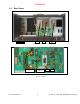
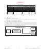
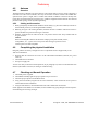
4.4.5 Backplane Fuses
Blade fuses (Maxi-Fuse) are used on the Radio assembly backplane:
Fuse Type
Dimensions – Inch (mm)
A B C
Maxi-Fuse 1.15 (29.21) 1.35 (34.29) .35 (8.89)
Fuse #
F1
Values 10A
Figure 9 - Maxi-Fuse
Preliminary