
Technical Manual

120 20191-001 Paragon-III Technical Manual
13
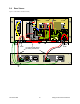
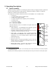
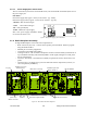
3.1.4 Speaker panel
The speaker panel is fitted with a four-Ω speaker.
Both series of radio assemblies share the same front panel fitted with an
RJ11 connector. This connector is used to allow programming the radio
from the front of the unit via a programming lead. This feature is exclu-
sive to the Series II modules.
If the speaker panel needs to be removed, a mirror programming port
connector is provided on the backplane.
Figure 7 - Speaker module
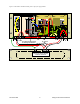
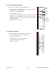
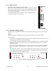
3.1.5 Dual Power Supply module
The Dual Power Supply module is made up of two separate power supply units coupled in a single
chassis.
Refer to:
Table 2 on page 9 for tabular listing of power supply LEDs indicators and Figure 8 below.
This module has:
•
Two “Power” red-colored pushbutton switches - Push in for ON and release out for OFF. Control
complete power distribution to the Radio assembly
•
Two “ON” LEDs - light green when push button(s) is (are) ON; DC power is distributed to radio
modules. Flash green in conjunction with the “OL” LED (flashing red) when an over voltage
condition is present.
•
Two “Stby”- Standby voltage LED, lights red when push button is off; AC power is applied but
DC is not distributed to radio modules. To remove presence of voltage, disconnect both power
cords.
•
Two “OL” LEDs - Monitor current overload, light steady red when supply exceeds current limit
set; nominally 25Amps (T808 model). Flashes red in conjunction with the ON LED (flashing
green) when an over voltage condition is present.
Figure 8 - Dual Power Supply Module front panel
®
Speaker Panel
programming
port
RX2RX1
OFF
SP EAK ER
SELE CT SWI TCH
OL Stby On
Power
OL Stby On
Power
T800
II
Slimline
®
Dual Power Supply Module