
Technical Manual

120 20191-001 Paragon-III Technical Manual
12
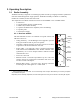
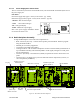
3.1.2 5W Transmitter module
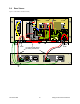
The Exciter’s front panel controls and indicators are:
•
Carrier Switch - momentarily keys the transmitter ON while
pressed (used for test purposes only).
•
On LED - is lit when transmitting
•
Line Sensitivity – not used.
•
Supply LED - is lit when DC power is applied. Fast Flashes
when linked with PGM800Win. Slow Flashes indicates VCO
(synthesizer) out of lock. Unequal Flashes indicates internal
communication error.
•
Microphone Socket – not used.
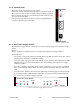
3.1.3 BDLC-III module
The BDLC-III's front panel connectors and indicators are:
•
2x DE-9 RS-232 ports for setup and user data
•
4x main unit status LED
•
2x Ethernet ports – for setup and user data
•
2x Ethernet LEDs (status & activity)
•
USB port – reserved.
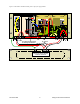
Carrier
Switch
On
LED
Supply
LED
Line
Sensitivity
Microphone
Socket
®
Exciter
Carrier
On
Line
Sensitivity
Supply
Microphone