
User's Manual

120 20194-102 Paragon3 – 700/800MHz User Manual
59
Multiple channels
(adjusting as shown for single channel above):
- T881 (700 MHz) Adjust the VCO loop to 10V using the middle frequency channel.
All channels should lie within the upper and lower limits of 16V and 3V respectively for the
T881.
Note:
Normally, the fast TX key option is installed and the synthesizer is always ener-
gized. In the case where that option was not fitted, key the transmitter by pressing
the front panel Carrier button to make the above adjustment possible.
6.2.2.3 Low-Frequency Balance Adjustment
Note:
• PGM800Win version 3.00 or later must be used. Electronic potentiometer (256 step) is used to
allow channel adjustment of two-point modulation (Low freq. balance).
1. Apply the following settings to the IFR:
– Receiver mode and Oscilloscope display (Source Demod out connector, DC coupled).
– IFR RX frequency to match the radio transmit frequency
– IF Filter set to 30 kHz
– Zoom the Deviation window: select 10 kHz Range and DC coupling.
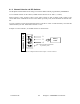
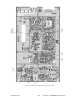
2. Select the active or, the lowest (in the case of multi-channel base) frequency channel (via dip switch,
refer to Figure 50).
3. From the web interface “Radio” page (“RF Test Tone”), select 100 Hz square wave – Press Execute.
Transmit a square wave and follow the procedure outlined in Table 6 at step 7.
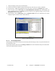
4. Via PGM800Win, press EPOTs button. Adjust IC220 “reference modulation” to obtain the best
square wave, no damping, no overshoot. (You can use either the mouse or up and down arrow keys).
Record the deviation read.
5. If transmission has not ended by itself, select “Cancel current test” to stop it. For single-channel unit,
proceed to step 8.
6. For multi-channel unit, select the highest frequency channel. From the web interface “Radio” page
(“RF Test Tone”), select 100 Hz square wave – Press Execute. Transmit a square wave and follow the
procedure outlined in Table 6 - Checklist B (General) at step 6. Record deviation again.
7. The difference in deviation between the two channels should be less than ±300 Hz. If not, re-adjust
IC220 to "average" the square wave shape on both channels until the spec is met.
8. To confirm the adjustment, select the active, or the lowest frequency channel. Compare the deviation
produced between 1000 Hz sine wave test tone and Random data test pattern
The difference between the test tone and the test pattern should be: < 2.5 kHz
For multi-channel unit, repeat this step for each frequency channel.
Select the active channel. From the web interface “Radio” page (“RF Test Tone”), select modulated –
Press Execute and follow the procedure outlined in Table 6 step 6. Make sure that deviation level read on
the IFR corresponds to model and bit rate in use as shown in the second column from the left. Re-adjust
deviation as necessary referring to Checklist B (Table 6) at step 6.