
User's Manual

120 20194-102 Paragon3 – 700/800MHz User Manual
48
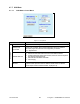
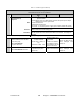
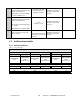
Table 5 - Checklist A (After installation)
CHECKLIST A (Paragon3)
Recommended Check out after Installation
Step ACTION
EXPECTED RESULTS at
25°C
MEASURE WITH IF NOT?
Normal Power-up
Sequence
BSC
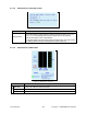
PWR LED lights red for four second, turns amber for one second, and stays
green thereafter.
TX LED flashes green once about fifteen seconds after power-up then keeps
flashing in-tune to the cycle marker
RX LED remains OFF
STATUS LED remains OFF
ETH 1 LED – if connection present – lights green. Flashes amber with activity
ETH 2 LED – If connection present – lights green. Flashes amber with activity
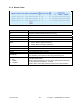
Receivers
GATE LED must remain steady red
SUPPLY LED must remain steady green
1
Transmitter
SUPPLY LED must remain steady green
ON LED lights red for one second, turns OFF for 10 seconds, and stays red
thereafter
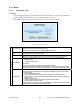
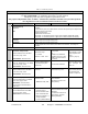
For steps below, on the Radio Î Set Up Web page, press the “test” button to enable Test Tone function
2
Power Amplifier Output Power
From the Maintenance unit WEB
“Test Tone” page,
Select Unmodulated
and press “Execute”
70 watts nominal
(settable down to 35W in fac-
tory)
Tolerance: +15% -20%
Service monitor set to
read power
or
100W in-line wattme-
ter installed as close
as possible to the unit
antenna connector.
Check for bad connec-
tions, damaged coax
cable, etc.
3
Transmitter Reflected Power
Select Unmodulated - Execute
< 5% of forward power or
as specified by System
Engineering.
10W in-line wattmeter
Check for bad connec-
tions, damaged coax
cable, etc.