
User's Manual

120 20194-102 Paragon3 – 700/800MHz User Manual
49
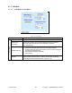
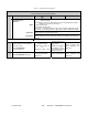
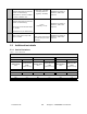
Table 6 - Checklist B (General)
CHECKLIST B (Paragon-3) General Check out
Paragon3 units are set and characterized at the factory to optimize performances.
It is not recommended to try readjusting units unless it is really required.
Misadjusting a unit may result in significant performance losses.
The proposed adjustments in the "IF NOT?" column below, should be tried ONLY if system data perform-
ance degradation is noticed combined with out-of-tolerance items.
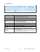
Step ACTION
Expected Results at 25°C
MEASURE WITH IF NOT?
Normal Power-up
Sequence
BSC
PWR LED lights red for four second, turns amber for one second, and stays green
thereafter.
TX LED flashes green once about fifteen seconds after power-up then keeps flash-
ing in-tune to the cycle marker
RX LED remains OFF
STATUS LED remains OFF
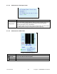
ETH 1 LED – if connection present – lights green. Flashes amber with activity
ETH 2 LED – If connection present – lights green. Flashes amber with activity
Receivers
GATE LED must remain steady red
SUPPLY LED must remain steady green
1
Transmitter
SUPPLY LED must remain steady green
ON LED lights red for one second, turns OFF for 10 seconds, and stays red
thereafter
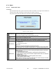
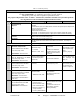
For steps below, on the Radio Î Set Up Web page, press the “test” button to enable Test Tone function
2
Transmitter Output Power
From the Maintenance unit WEB
“Test Tone” page, select
Unmodulated – Press Execute
Adjustment range:
35 - 70 watts
Tolerance: +15% -20%
Service monitor set to
read power
or
100W in-line wattmeter
installed as close as pos-
sible to the unit antenna
connector.
Adjust “Power” on the
power amplifier front
panel
(Figure 4, page 6)
3
Transmitter Reflected Power
From the Maintenance unit WEB
“Test Tone” page, select
Unmodulated – Press Execute
< 5% of forward power or
as specified by System
Engineering.
10 W in-line wattmeter
Check for bad connec-
tions, damaged coax
cable, etc.
4
Carrier Frequency Error
From the Maintenance unit WEB
“Test Tone” page, select
Unmodulated – Press Execute
< ±300 Hz
Service monitor set to
read frequency error
Adjust TCXO (IC700)
(see inside Exciter
module at, Figure 51
5
TX Deviation (kHz)
From the Maintenance unit WEB
“Test Tone” page, select
Modulated – Press Execute
Carrier will be modulated with a
1 kHz tone.
Refer to Table 7 for TX
Deviation details
Tolerance is +5%, -10%
Service monitor set to
read deviation.
(IF filter set to Mid or 30
kHz position)
6
Low Frequency Balance
From the Maintenance unit WEB
“Test Tone” page, select
Random data – Press Execute
a) Record deviation level
read from step 5
b) Record deviation read
from TX Random test
c) Difference between a)
and b) should be:
< 2.5 kHz (SRRC16FSK)
Service monitor set to read
deviation
(IF filter set to Mid or 30
kHz position, all audio
filtering disabled )