
User Manual
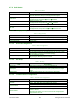
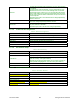
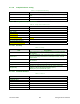
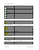
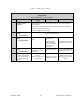
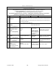
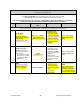
Table Of Contents
- PRODUCT OVERVIEW
- Installation
- Operating Description
- Operation & Configuration
- Trouble-Shooting and Testing
- Radio Programming and Adjustments
- Specifications

120 20191-100a Paragon-III User Manual
28
Table 21 - Checklist B (General)
CHECKLIST B (Paragon-III)
General Check out (part1 of 2)
Paragon-III units are set and characterized at the factory to optimize performances.
It is not recommended to try readjusting units unless it is really required.
Misadjusting a unit may result in significant performance losses.
The proposed adjustments in the "IF NOT?" column below, should be tried ONLY if system data
performance degradation is noticed combined with out-of-tolerance items.
Step ACTION
Expected Results at 25°C
MEASURE WITH IF NOT?
1
Normal Power-up
Sequence
PWR LED lights red for one second, turns amber for one second, and stays green there-
after.
TX LED flashes green once about eight seconds after power-up then keeps flashing in-
tune to the cycle marker
RX and STATUS LEDs remain OFF
2
Connect and save unit
config
Press CDip Get button
as per CDip Help content
3
Transmitter Output
Power
Press TX ON (Unmod)
70 watts
±10%
Service monitor set
to read power
or
100W in-line watt-
meter installed as
close as possible to
the unit antenna
connector.
Adjust “Power” on the front
panel of the “Power Amp”
4
Transmitter Reflected
Power
Press TXON (Unmod)
< 5% of forward power or as
specified by System Engi-
neering.
10 W in-line
wattmeter
Check for bad connections,
damaged coax cable, etc.
5
Carrier Frequency Er-
ror
Press TX (Unmod)
< ±300 Hz
Service monitor set
to read frequency
error
Adjust TCXO (IC700)
(see inside Exciter module at,
Figure 24
6
TX Deviation (KHz)
Press
TX (modulated)
Carrier will be modulated
with a 1 kHz tone.
±8.0 kHz
Tolerance is +5%, -10%
Service monitor set
to read deviation.
(IF filter set to Mid
or 30 kHz position)
Refer to tech support