
User Manual
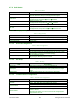
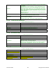
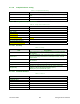
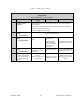
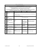
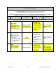
Table Of Contents
- PRODUCT OVERVIEW
- Installation
- Operating Description
- Operation & Configuration
- Trouble-Shooting and Testing
- Radio Programming and Adjustments
- Specifications

120 20191-100a Paragon-III User Manual
2
7
Table 20 - Checklist A (After installation)
CHECKLIST A
(Paragon-III)
Recommended Check out after Installation
Step ACTION EXPECTED RESULTS
at 25°C
MEASURE WITH IF NOT?
1
Normal Power-up
Sequence
PWR LED lights red for one second, turns amber for one second, and stays
green thereafter.
TX LED flashes green once about eight seconds after power-up then keeps
flashing in-tune to the cycle marker
RX and STATUS LEDs remain OFF
2
Connect and save unit
config
Press CDip Get button
as per CDip Help content
3
Power Amplifier Output
Power
Press TXON (Unmod)
70 watts
±10%
Service monitor set
to read power
or
100W in-line watt-
meter installed as
close as possible to
the unit antenna
connector.
Check for bad connections,
damaged coax cable, etc.
4
Transmitter Reflected
Power
Press TXON (Unmod)
< 5% of forward power or
as specified by System
Engineering.
10W in-line wattme-
ter
Check for bad connections,
damaged coax cable, etc.
5
RF Link test
Use the mobile address
function and “Send” but-
ton to dynamically test
the link
Look for
“Delivery confirmed” on
the Status bar
Refer to 5.3.1 and to
CDip Help content.
Mobile is out of range
Refer to factory technical
support.