
User Manual
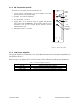
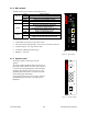
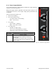
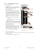
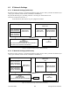
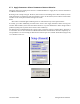
Table Of Contents
- PRODUCT OVERVIEW
- Installation
- Operating Description
- Operation & Configuration
- Trouble-Shooting and Testing
- Radio Programming and Adjustments
- Specifications

120 20191-100a Paragon-III User Manual
13
3.1.4 BSC module
The BSC's front panel connectors and indicators are:
Green Normal operation
Amber Step 2 in uMon boot-up – lights for <1 sec.
PWR LED
Red Step 1 in uMon boot-up – lights for <1 sec.
Green Flashes for each data packets received
RX LED
Red Discard RX packet (factory-use)
Green Flashes for each data packets transmitted
Amber
Flashes for each data packets transmitted
(check for lost Host connection)
Red
Continuoulsy ON for TXON test (max. 20 secs.)
Flashes ON for CWID key-up event
TX LED
Off Check if in “AirLink down mode”
Green Flashes each time PF1 or PF2 is pressed
STATUS
Amber
Flashes each second PF1 is kept pressed
Toggles “AirLink down mode” after 4 seconds
• 2x DE-9 RS-232 ports for setup and user data
• 1X rocker switch ( positions PF 1 and 2) to select various test modes
• 2x Ethernet ports – for setup and user data
• 2x Ethernet LEDs (status & activity)
• USB port – reserved.
Figure 10 - BSC module
3.1.5 Speaker panel
The speaker panel is fitted with a four-Ω
speaker.
All series of radio assemblies share the same front
panel fitted with an RJ11 connector. This connector
is used to allow programming the radio transmitter
module (only) from the front of the unit via a pro-
gramming lead. This feature is exclusive to the Se-
ries II and Paragon III modules.
If the speaker panel needs to be removed, a mirror
programming port connector is provided on the
backplane.
Figure 11 - Speaker module
®
Speaker Panel
programming
port
RX2RX1
OFF
SPEAKER
SELECT SWITCH
®
PWR
TX
BSC
ETH 2
RX
USB
ETH 1
COM 2
COM 1
STATUS