
User Manual
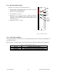
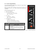
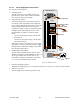
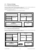
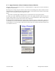
Table Of Contents
- PRODUCT OVERVIEW
- Installation
- Operating Description
- Operation & Configuration
- Trouble-Shooting and Testing
- Radio Programming and Adjustments
- Specifications

120 20191-100a Paragon-III User Manual
12
3.1.2 5W Transmitter module
The Exciter’s front panel controls and indicators are:
• Carrier Switch - momentarily keys the transmitter ON while
pressed (used for test purposes only).
• On LED - is lit when transmitting
• Line Sensitivity – not used.
• Supply LED - is lit when DC power is applied. Fast Flashes
when linked with PGM800Win. Slow Flashes indicates VCO
(synthesizer) out of lock. Unequal Flashes indicates internal
communication error.
• Microphone Socket – not used.
F
Figure 9 – 5W Exciter module
3.1.3 70W Power Amplifier
The power amplifier is maintenance free, only LED indications and a front panel adjustment are
provided for the user.
Refer to Figure 3 on page 6 above, for the locations of the indicators and the power adjustment.
Table 2 - 70W Power Amplifier indicators
LED Function
DC / ON Lights green when power is applied
RF / ON Lights yellow when input RF power is applied
OVER / TEMP Lights red when temperature-based shutdown is triggered
Carrier
Switch
On
LED
Supply
LED
Line
Sensitivity
Microphone
Socket
®
Exciter
Carrier
On
Line
Sens itivity
Supply
Microphone