
User's Manual


5.4 Fault Finding
M889-00
02/10/95 Copyright TEL
5.4 RF Checks
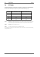
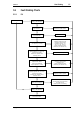
The PA Fault Finding Chart (Section 5.5.1) provides a systematic approach for locating a
fault in the RF circuitry. Use this chart in conjunction with Figure 5.1, which shows the
locations of the 50Ω input and output test points for RF transistors Q1-Q6.
Note 1:
Always
test individual PA stages at the 50Ω test points, located at the ends
of the semi-rigid transmission lines furthest away from the RF transistors.
Note 2:
Always
test Q1 and Q2 as a pair.
Note 3:
Use 50Ω semi-rigid coax for the flying test leads.
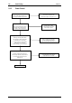
For problems with the power control circuitry, refer to the Power Control Fault Finding
Chart (Section 5.5.2).
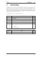
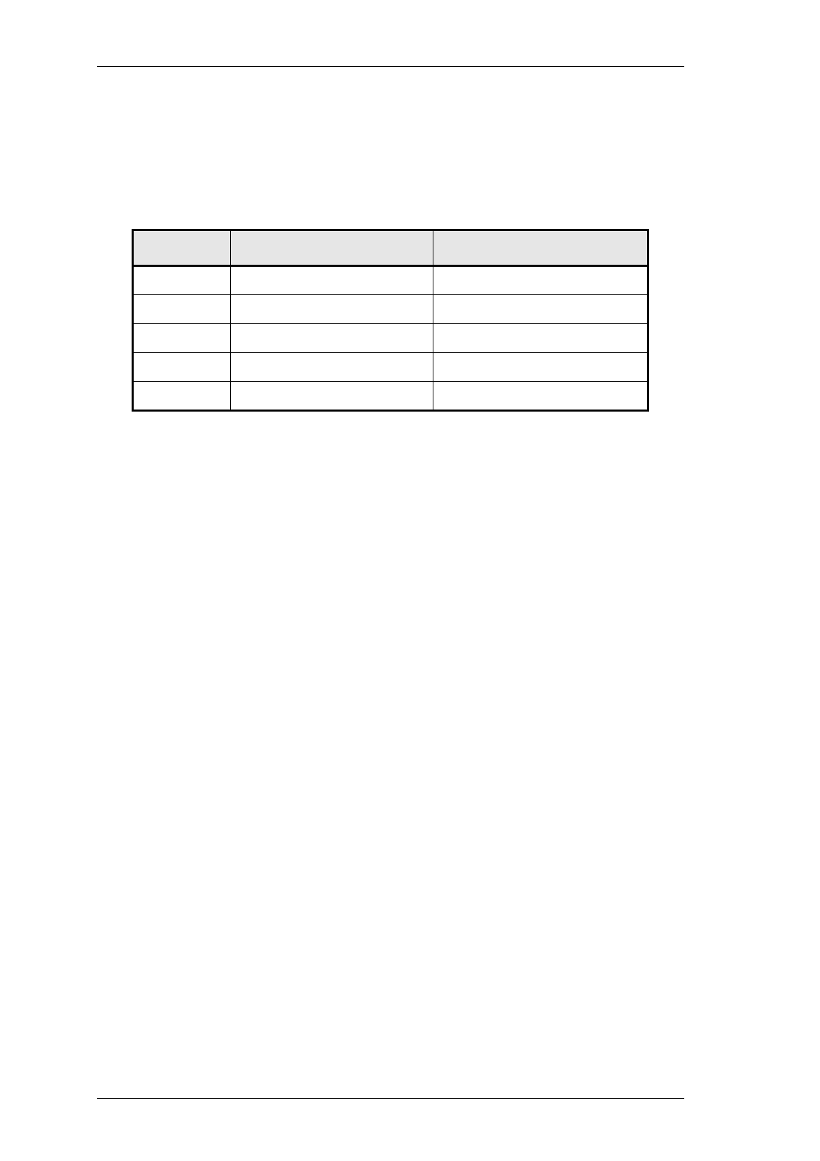
Transistor Input Transmission Line Output Transmission Line
Q1-Q2 L1 L12
Q3 L16 L22
Q4 L26 L32
Q5 L33 L39
Q6 L43 L49