
User's Manual


M889-00
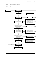
Fault Finding 5.3
Copyright TEL 02/10/95
5.1 Visual Checks
Remove the cover from the T889 and inspect the PCB for damaged or broken com-
ponents, paying particular attention to the surface mounted devices (SMD's).
Check for defective solder joints. If repair or replacement is considered necessary,
refer to Sections 3.3, 3.4, 3.5 and 3.6.
5.2 Component Checks
If a transistor is suspected of faulty operation, an indication of its performance can be
assessed by measuring the forward and reverse resistance of the junctions. First make
sure that the transistor is not shunted by some circuit resistance (unless the device is
completely desoldered). A 20k ohm/V or better multimeter should be used for taking
the measurements, using only the medium or low resistance ranges.
The collector current drawn by multi-junction transistors is a further guide to their per-
formance.
If an IC is suspect, the most reliable check is to measure the DC operating voltages. Due
to the catastrophic nature of most IC failures, the pin voltages will usually be markedly
different from the recommended values in the presence of a fault. The recommended
values can be obtained from either the circuit diagram or the component data catalogue.
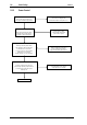
5.3 DC Checks
Check that +13.8V is present on the collectors of Q2, Q3, Q4, Q5 and Q6. Make
this measurement when the transmitter is not keyed.
Check that approximately 8-13.8V is present on the collector of Q1 (the level is
dependent on RV69 being set to maximum).
Check that +13.8V is present at pin 4 of IC3.
Check that approximately +12V is present at pin 4 of IC1 (the level is dependent
on RV69 being set to maximum).
Check that +7.0V is present at the output of regulator IC2.