
User's Manual
3.10 Introduction To Servicing
M889-00
02/10/95 Copyright TEL
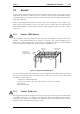
3.5 To Remove The PCB From The Heatsink
Most components are soldered topside only, but in some cases access to the underside of
the PCB is necessary.
Remove the D-range connector.
Disconnect the power feed to the fan.
Remove the 13 PCB retaining screws (2 are hidden beneath the harmonic filter
shield).
Remove the transistor mounting screws.
Remove the mounting screws for the TO-220 devices:
R6, R7, R9, R16, R17, R17a and R18.
Remove the retaining screws for the wireline couplers (L13, L14, L15, L40, L41 and
L42).
Remove the output 50 ohm coaxial connector by unscrewing it from the heatsink
casting and desoldering it from the PCB.
Disconnect the input 50 ohm coaxial cable by unplugging it at the PCB.
Disconnect the battery positive and negative feed wires from the PCB.
Disconnect the alarm and metering wires from the PCB.
Lift the PCB gently from the heatsink to gain access to the underside of the PCB.
Caution:
Do not operate the PA with the PCB detached as the heatsink is used
for earthing and for the dissipation of heat generated within the tran-
sistors.
To replace the PCB, reverse the order of removal, taking care that the wiring is cor-
rectly routed and is not subjected to 'pinching'.
3.6 To Remove Cased Mica Capacitors
Cased mica capacitors can be removed by heating the top with a heavy-duty soldering
iron and gently lifting the capacitor off the PCB with a solder-resistant spike or equiva-
lent.