
User's Manual

3.8 Introduction To Servicing
M889-00
02/10/95 Copyright TEL
3.4 To Replace PA Transistors
Caution:
As the location of certain components in the PA is critical to perform-
ance, it is important that any components removed or disturbed are
refitted in
EXACTLY
the same position.
Caution:
Do not solder the tabs before torquing down otherwise the device may
be broken.
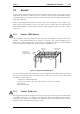
3.4.1 Capacitor /Transistor Spacing
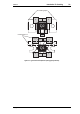
Refer to Figure 3.2.
3.4.1.1 Q1 (2SC2933 Pre-Driver)
Before attempting to remove Q1, measure the distance between the capacitors
labelled “c” and the transistor body (measurement “a”) so that the capacitors can
be replaced in
exactly
the same position.
Note:
Be sure to measure between the transistor body and the
tabs
(not the body)
of the capacitors.
Position the capacitors labelled “b” hard up against the transistor body.
3.4.1.2 Q2, Q3, Q4, Q5 & Q6 (SD1414)
Position all capacitors labelled “b” hard up against the transistor body.
3.4.2 Replacement Procedure
Desolder the tabs (and grounding clips if an SD1414) by heating with a soldering
iron and lifting away from the PCB with a thin stainless steel spike, or screw-
driver.
Unscrew the transistor and remove the device.
Smear the face of the replacement device with heatsink compound and tighten it
securely (torque setting 6lb-in./0.7Nm) to the heatsink. If you are replacing an
SD1414, remember to fit new grounding clips.
Solder the tabs.
Replace each capacitor as instructed in Section 3.4.1.