
Technical Manual

120 20170-200 Paragon
PD
Technical Manual46
6.4.2.2 Synthesizer Alignment
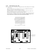
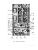
Single channel: Connect the multimeter to the long lead of L1 in the VCO (this measures the syn-
thesizer loop voltage).
1.
T855 (UHF) Tune VCO trimmer C6 for a synthesizer loop voltage of 10V DC.
2.
T835 (VHF). Tune VCO trimmer CV1 for a synthesizer loop voltage of 9VDC.
Multiple channels:
1.
T855 (UHF) Adjust the VCO loop to 10V using the middle channel.
2.
T835 (VHF) Adjust the VCO loop to 9V using the middle frequency channel.
3.
All channels should lie within the upper and lower limits of respectively
All channels should lie within the upper and lower limits of 16V and 3V respectively for the T855
and within 13V and 5V for the T835.
6.4.2.3 Front-End Alignment
1.
IFR COM120B settings:
a)
Connect a 3 feet long double shielded cable (N-M to BNC-M) between the IFR T/R out-
put and the receiver antenna connector.
b)
Select the generator mode (GEN button) and set to the main receiver channel frequency
c)
Select and turnon GEN2
d)
Set the FM Deviation to ±3kHz (full channel) or ±1.5kHz (half channel) using 1KHz sine
e)
Select SINAD meter
f)
Use a X1 scope probe connected to SINAD input and monitor the Discriminator O/P on
the backplane at SK1 pin 6 (RX-audio1). Alternately, it is also possible to monitor at the
receiver TP314 (T855) or at the receiver IC350 pin 7 (T835).
2.
Adjust the helical resonators for best SINAD: #FL410 and #FL420 (T855) or L410, L420,
L460 and L470 (T835).
3.
Continually decrease the RF level to reach 12dB SINAD, then re-do step 2) & 3) again.
(minimum requirement to reach is 12dB SINAD for -110dBm)
4.
Perform the SINAD linearity tests described in paragraph 6.4.2.4. If it fails to pass the re-
quirement, contact your Dataradio technical support.
WARNING: Do NOT attempt to re-tune the IF stages
(i.e. L310 to L390 for T855, CV318 or L330 to L360 for T835).
These adjustments do not need to be re-adjusted after frequency re-
programming. Touching these coils will have a direct impact on the modem
DSP coefficient settings and may reduce significantly the radio performances
over data.
6.4.2.4 SINAD and Linearity Check
1.
Apply the following settings to the IFR:
a)
Generator mode, Output T/R
b)
IFR TX frequency to match the main radio RX frequency
c)
Filter set to wide band (no audio filter)