
Technical Manual

120 20170-200 Paragon
PD
Technical Manual25
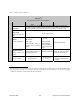
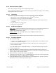
Table 9 - Checklist A (after installation)
CHECKLIST A
(Paragon
PD
)
Recommended Check out after Installation
Step ACTION EXPECTED RESULTS at
25
°
°°
°
C
MEASURE WITH IF NOT?
1
Normal Power-up
Sequence
BDLC
PD
beeps once, all LEDs come ON for about four seconds, the green LEDs
then flash in a “ripple” pattern for close to two seconds. All LEDs go OFF except the
CK that should flash 6 to 8 times per second. For functions, see section 3.2.1.2
2
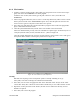
Connect and save
unit config
Press RIS
Get
but-
ton
as per section 4.4.1
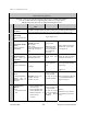
3
Transmitter Output
Power
Press
TX (Unmod)
VHF/UHF
: 100 watts
800
: 70 watts
+10%, -10%
Factory-settable down to
10 watts as per customer
request.
Service monitor set to
read power
or
150W in-line watt-
meter installed as
close as possible to
the unit antenna con-
nector.
1
Refer to Checklist
B
4
Transmitter
Reflected Power
Press
TXON (Un-
mod)
<5% of forward power or as
specified by Syst. Eng.
10W in-line wattmeter
Check for bad connections,
damaged coax cable, etc.
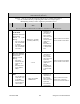
5
RF Link test
"Ping" a mobile
“Ping Successful”
as per sections
4.4.4.3
- Mobile is out of range
- Refer to factory technical
support.
1
(unless unit has been set a lower value). Note that readings less than 100 watts for VHF/UHF or 70 watts for 800 MHz models,
may be due to losses in cables used for testing. Check also your wattmeter frequency calibration curve. Do not be too ready to
condemn the transmitter or the RF feedline & antenna installation.