
Technical Manual

120 20170-200 Paragon
PD
Technical Manual13
3.2.1.1.2.1 Clearing Errors
Major and minor error LED indications remain lit
on the front panel until:
•
The unit is RESET
•
The unit is powered OFF and ON again
•
PF 1 is pressed
The PF 1 switch can be pressed at any time to
clear an error display without affecting normal
operations.
3.2.1.1.2.2 Test Transmissions
To select a pattern and begin transmission, start
by pressing and holding PF1. It beeps once, all
five RS232 LEDs light; listen for a second beep
followed by a third beep. After two seconds, the
unit beeps and goes in “TX Select” mode with
only the three rightmost RS-232 LEDs now used
as selection indicators. Only release PF1 after
the third beep.
Following release:
•
Start of selection must be made within two
seconds. If not, the unit will default to pat-
tern one and start test transmitting.
•
PF1 may be pressed more than once. The
number of times it is pressed determines the
type of pattern that will be transmitted ac-
cording to Table 3
•
Each pressing of PF1 extends the two-second
timer.
•
The three rightmost RS-232 LEDs display
are used to indicate TX mode selection as
shown in Table 2.
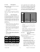
Table 2- TX mode selection LEDs indications
Binary TX mode LED indicationsTX pattern
selected
FT LED RD LED TD LED
1 Off Off On
2 Off On Off
3 Off On On
4 On Off Off
5 On Off On
6 On On Off
7OnOnOn
Once the type of transmission is selected, stop
pressing PF1, allow the two-seconds timer to run
down. Automatically, the BDLC
PD
turns its
transmitter ON, sends the selected “test pattern”
for 55 seconds and turns its transmitter OFF.
The TX LED in the RF group of indicators lights
in red while test transmitting. Pressing PF1 while
the 55 seconds test is in progress stops the test.
At the end of test transmission, BDLC
PD
opera-
tion returns to normal and the RX LED lights in
green (monitoring normal transmitter activity).
Table 3 - Test Transmissions
Paragon
PD
# times
PF1 is
pressed
16000 b/s 25600 b/s
1 2400 Hz Dotting* 3200 Hz Dotting*
2 Do not use Do not use
3 100 Hz Square wave 100 Hz Square wave
4 Random data Random data
5 Unmod Unmod
6
1000 Hz sine
beacon mode
1000 Hz sine
beacon mode
7
1000 Hz sine wave
Adjustment tone
1000 Hz sine wave
Adjustment tone
*
Dotting with reduced amplitude
Notes:
-
A dotting pattern consists of alternating sequence of
1’s and 0’s
-
The square wave is used for balancing transmitter
low frequency response
-
The 1000 Hz sine can be used for transmitter distor-
tion measurements.
-
Pattern 6 produces a transmission of 55 seconds
followed by 55 seconds of silence. Initial transmis-
sion in a sequence may be shorter than 55 seconds.
TX LED stays steadily red for duration of the test.
Press PF1 to terminate beacon mode.
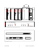
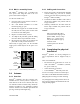
3.2.1.1.2.3 RS-232 LED Function
Selection
The PF 1 button is used to select the RS-232
display mode as follows:
•
If pressed ONCE (do not hold pressed):
-
Clears Alarm indications
-
CK LED stops flashing for 2 seconds
-
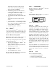
During this time, one or all of the
RS-232 numbered LEDs (see Figure 13)
will light. If one LED lights, it denotes
the port to which the subsequent display
applies. If all numbered LEDs light, it
denotes that the normal 3-port display
mode is active.
The selected display remains active until