
Technical Manual

120 20170-200 Paragon
PD
Technical Manual7
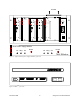
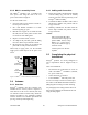
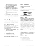
2.3.1 Radio Assembly Power
Referring to Figure 3, the Radio assembly unit
receives two separate 13.8 VDC power inputs
from a “T800 Slimline” dual power supply typi-
cally rack-mounted right below the main assem-
bly radio chassis.
The T800 is made up of two separate power
supply units joined in a single chassis:
•
A T807 using convection cooling is rated up
to 15A. It supplies all the radio modules
other than the Power Amplifier.
•
A T808 using convection and fan cooling is
rated up to 25A. It supplies only the Power
Amplifier module.
Normally used at room ambient temperatures,
they can operate within specifications over a
range of –10 to +60 °C.
Note: Internal over-temperature protection
shuts down the main transformer above
105 degrees Celsius.
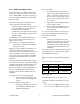
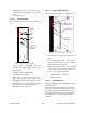
Both power supply modules are internally con-
nected to ground via their individual, rear-
connected, seven-foot standard 120 VAC power
cords. Nevertheless, each requires a separate
secure electrical ground connection. Individual
grounding tabs are provided next to the power
connectors.
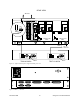
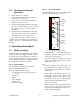
Similarly, the Radio Assembly chassis requires a
secure ground connection. A threaded grounding
binding post fitted with a knurled binding-nut is
provided on the chassis next to DC input 2.
Separate grounding leads with appropriate con-
nectors are supplied (either in the courtesy
small-parts kit or with one end fastened to the
equipment.
A- For each of the power supply modules:
1.
Fit one end of the grounding lead’s
push-on connector onto the ground-
ing tab.
B- For the Radio Assembly chassis:
1.
Install the grounding lead’s lug over
the binding post and firmly hand-
tighten the binding-nut.
For both A and B
2.
Fit the slotted connector (on the other
end of each of the grounding connector)
under a conveniently located screw on
the rack frame or other support surface.
Scrape away paint if needed to ensure
clean contact.
3.
Apply anti-corrosion compound where
paint scraping was done.
4.
Ensure by testing continuity that a se-
cure electrical and mechanical connec-
tion is achieved.
If a –DC rail (0V) is installed as part of the sys-
tem, the grounding leads may alternatively be
fitted to the rail terminal.
Caution:
Improper grounding between power
supply case and rack frame may result
in harmful voltage potentials and/or
miscellaneous power supply switching
noise problems in both receivers and
transmitter.
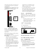
Press both red power buttons located on the front
of the module to have complete power distribu-
tion to the Radio assembly.
The power supply front panel LEDs indications
are:
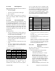
Table 1 - Power Supply LEDs Indications
LED Color Indication
On Green Power enabled *
Stby Red Power disabled *
OL Steady Red Current Overload
On & OL
Flashing green and
red respectively
Over voltage
*
To remove voltage from the power supply PCB, disconnect
the main power cords.
For LEDs descriptions, see section 3.2.1.2
The Radio assembly is fused at the rear of the
chassis:
•
Fuse 1 is a 32-volt MDL (slow-blow) 10A
•
Fuse 2 is a 32-volt MDL (slow-blow) 30A