
User's Manual
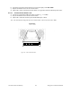
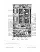
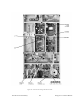
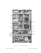
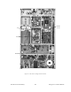
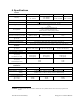
Table Of Contents
- PRODUCT OVERVIEW
- Installation
- Operating Description
- Trouble-Shooting and Testing
- Radio Programming and Adjustments
- Series II Radio Programming
- Series II Radio Tuning
- Specifications

120 20170-301 Preliminary Paragon
P
D
Technical Manual
37
b)
Toggle the front panel switch until the top line of the display reads RFL PWR.
c) Key the transmitter T881's Exciter Carrier button.
d) Adjust TPL's VR7 so that the front panel meter is in agreement with the calibrated power meter.
5.2.5.7 Reverse Power Alarm Level
a) Connect an unterminated 3dB pad to the PA output (e.g. 3:1 VSWR).
e) Key the transmitter T881's Exciter Carrier button.
b) Adjust TPL's VR3 until the front panel SWR LED begins to flash
Note: The LED should extinguish when the normal load is connected (connected to IFR).
Figure 26 - (TPL) LMS Rear Panel
VR8 VR4 VR5 VR3 VR6 VR7 VR1 SW1