
User's Manual
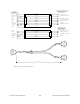
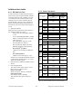
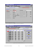
Table Of Contents
- PRODUCT OVERVIEW
- Installation
- Operating Description
- Trouble-Shooting and Testing
- Radio Programming and Adjustments
- Series II Radio Programming
- Series II Radio Tuning
- Specifications

120 20170-301 Preliminary Paragon
P
D
Technical Manual
19
4. Trouble-Shooting and Test-
ing
The checks described below should be done at
time of installation, annual intervals or whenever
deterioration in performance is noted.
4.1 Equipment Required
• In-line watt meter (150W & 10 W ranges)
• Radio service monitor (IFR-120B with
option 03: 30KHz IF filter or equivalent).
• RG-214 or RG-223 cable with N-Type male
connector to connect Paragon
PD
to the serv-
ice monitor.
• WinRIS 3.11 or later
1
Important note: Before proceeding make sure
that the service monitor has been calibrated
recently and has warmed up for at least the
time specified by its manufacturer.
Some reported frequency and deviation prob-
lems have actually been erroneous indications
from service monitors that have not adequately
warmed up. This is particularly likely when field
service is done during winter months
.
1
To learn how to launch the Windows-based
software alignment and system-testing tool
WinRIS, please refer to the readme.txt file on
the application’s installation diskette.
For functional details of the numerous buttons
and menu-selectable items available, please
refer to the program’s context sensitive help. It
is also possible to access the help information
via the F1 key.
4.2 Recommended Checks
A) After an installation
1. LED Indications
2. Using WinRIS, Save “unit config” to a file
3. Transmitter Output Power
4. Transmitter Reflected Power
5. RF Link test between Paragon
PD
and
mobile unit(s)
B) For annual maintenance & trouble-
shooting
Same checks as A) plus:
6. Carrier Frequency Error
7. TX Deviation
8. Low Frequency Balance
9. 12 dB SINAD
10. Receiver distortion
11. RSSI check
Transmissions for some of the tests above can be
initiated by pressing the PF1 membrane button
located on the front of the BDLC
PD
. For details
on its use, refer to Table 3 and section 3.2.1.3 on
page 14.