
User's Manual
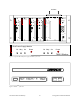
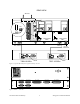
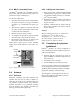
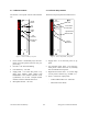
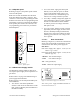
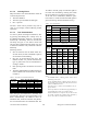
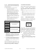
Table Of Contents
- PRODUCT OVERVIEW
- Installation
- Operating Description
- Trouble-Shooting and Testing
- Radio Programming and Adjustments
- Series II Radio Programming
- Series II Radio Tuning
- Specifications

120 20170-301 Preliminary Paragon
P
D
Technical Manual
13
3.1.2 Radio Assembly, rear panel
3.1.2.1 Backplane PCB
Referring to Figure 3, two main backplanes are
used. Their main components are:
• RJ11 connector – Mirrors the one on the
front of the Speaker panel (series con-
nected to both backplanes). Used for pro-
gramming the Radio Assembly whenever
the speaker panel has been removed.
• DB-25M plug at PL1 (one side of the
“Y” cable on each PCB) – used to supply
the receive signal to the BDLC
PD
’s single
“EXT.RADIO/TEST” DB-25F plug.
• Two channel-select DIP switches (SW1
and SW2)
This feature is exclusive to the Series II model.
• Cooling fan driver – CN2 located on
backplane connects to the horizontally-
mounted fan on top of the Radio assem-
bly and activated by BDLC’s PTT signal.
• Coaxial relay driver – not used.
3.2 BDLC
PD
The rack-mounted BDLC
PD
is housed in a steel
case. It has no user serviceable parts. Unit’s con-
figuration is stored in flash memory (EEPROM).
3.2.1 BDLC
PD
Front panel
Referring to Figure 2, the front panel of the
BDLC
PD
has two cutouts across its length.
A- The left cutout groups the unit’s type label and
ten LED indicators:
• The S3 label designates the BDLC
PD
as a
“three Serial-port” model
(Ports 4 and 5 are reserved for future use)
• The RF group of 3 LEDs
• The RS-232 group of 5 LEDs
• A single CK LED
• The ALARMS group of 4 LEDs
B- The right cutout groups two tactile (mem-
brane) switches (PF1 and RESET).
3.2.1.1 Front Switches
Referring to Figure 11, the BDLC
PD
uses two
membrane-type switches labeled:
• RESET
• PF 1
These switches indicate contact by emitting a
short BEEP tone when pressed.
Figure 11 - BDLC
PD
membrane switches
3.2.1.1.1 Reset
Pressing Reset produces the same result as pow-
ering OFF and ON again. It restarts the micro-
processor, the peripherals and invokes the on-
board diagnostics. BDLC
PD
’s radio modules’ in-
ternal flash-memories are read and their values
are loaded in system SRAM CPU flash-memory.
Normally, pressing Reset results in one short
BEEP tone followed by all LEDs coming ON for
about four seconds. Then, the LEDs flash in a
“ripple” pattern for close to two seconds indicat-
ing diagnostics are in progress. At the end of this
period, all LEDs should be OFF except CK that
should flash about six to eight times per second.
Expect an additional two seconds delay for CK to
start flashing and the UF indicator to come ON if
the radio assembly is not connected or not pow-
ered (see section 3.2.1.5.4 for Alarm details).
3.2.1.1.2 PF 1
PF 1 is a multi-function switch:
• It clears LED error indications
• It initiates test transmissions
• It sets the function of the RS-232 LEDs
PF1
RESET