
User's Manual
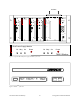
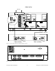
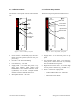
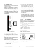
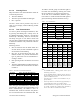
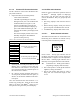
Table Of Contents
- PRODUCT OVERVIEW
- Installation
- Operating Description
- Trouble-Shooting and Testing
- Radio Programming and Adjustments
- Series II Radio Programming
- Series II Radio Tuning
- Specifications

120 20170-301 Preliminary Paragon
P
D
Technical Manual
11
3.1.1.2
Exciter module
The Exciter’s front panel controls and indicators
are:
Figure 7 - Exciter module, front panel
• Carrier Switch - momentarily keys the trans-
mitter ON while pressed (used for test pur-
poses only).
• On LED - is lit when transmitting
• Line Sensitivity – not used.
• Supply LED - is lit when DC power is ap-
plied. Fast Flashes when linked with
PGM800Win. Slow Flashes indicates VCO
(synthesizer) out of lock. Unequal Flashes
indicates internal communication error.
• Microphone Socket – not used.
3.1.1.3 Power Amp module
The Power Amp front panel and indicators are:
Figure 8 - Power Amp module, front panel
• Supply LED - is lit when DC power is ap-
plied.
• Low Forward Power LED - is lit when for-
ward power is below the level set, normally
80% of nominal forward power.
• High Reverse Power LED - is lit when high
reverse power is detected (e.g. VSWR= 3:1).
• Power - sets the PA output power:
- VHF & UHF models: 20 - 100 Watts
- 800 model: 20-70 Watts
Carrier
Switch
On
LED
Supply
LED
Line
Sensitivity
Microphone
Socket
®
Exciter
Car rier
On
Line
Sens it ivity
Supply
Microphone
®
Power Amplifier
Low Forward Power
Supply
High Rev erse Power
Po w e r
Supply
LED
Low Forward
Power LED
High Reverse
Power LED
Power
Adjustment