
User's Manual

120 20170-200 Paragon
PD
Technical Manual27
CHECKLIST B (Paragon
PD
)
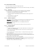
General Check out (part2 of 2)
Paragon
PD
units are set and characterized at the factory to optimize performances.
It is not recommended to try readjusting units unless it is really required.
Misadjusting unit may result in significant performance losses.
Step ACTION EXPECTED RESULTS at
25
°
°°
°
C
MEASURE WITH IF NOT?
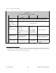
Set the service monitor to generate on the selected receive frequency. Verify alternately for both receivers.
The carrier should be modulated with a 1.0 kHz tone at deviation level specified below:
8
12 dB SINAD
(Dataradio wide band
measurement
method: no audio
filtering)
- For Full channel
unit, set deviation
to ±3 kHz.
- For Half channel
unit, set deviation
to ±1.5 kHz
Better than -110 dBm
(including cable loss)
- Backplane cor-
responding to
the receiver
being verified:
SK1, Pin 6 (see
Figure 30)
- Service monitor
(IFR) set to
SINAD
- IFR IF filter set
to MID position
or 30 kHz wide
filter.
Refer to section 6.2 for Series
I and to section 6.4 for Series
II
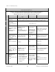
9
Receiver distortion
(Dataradio wide band
measurement
method: no audio
filtering)
- Set service
monitor RF Gen
output to –70
dBm
-
Deviation level
as per SINAD
above.
≤ 5.5 %
- Backplane cor-
responding to
the receiver
being verified:
SK1, Pin 6 (see
Figure 30)
- Service monitor
(IFR) set to
SINAD
- IFR IF filter set
to MID position
or 30 kHz wide
filter.
Refer to section 6.2 for Series
I and to section 6.4 for Series
II
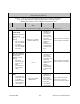
10
RSSI
- Vary the RF level
output from –120
to –80 dBm
- Measure voltage
at each RSSI re-
ceiver ouputs
- 2VDC @ -110dBm
- 10dB/V ±0.2V
- Backplane cor-
responding to
the receiver
being verified:
SK1, Pin 5 (see
Figure 30)
- DC Voltmeter
measurement
Refer to section 6.2.2.5 for
Series I and to sections
6.4.2.5 or 6.4.2.6 for Series II