
User's Manual

120 20170-200 Paragon
PD
Technical Manual17
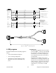
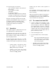
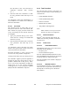
Figure 15 - BDLC
PD
Y cable and pinout
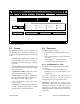
4. RIS program
The Radio Installation Software (RIS) program is
used to:
•
Check and troubleshoot Paragon
PD
.
•
Save an existing configuration.
•
Upload files for field configuring of units
(Requires intervention with technical sup-
port).
Important note:
The aggregate total baud rate for all active
ports on a BDLC
PD
must not exceed 30,000
for Paragon
PD
. Sustained simultaneous op-
eration on devices 1 and 3, using the fac-
tory settings for these ports, may result in
lost characters.
Using the factory settings, device 3 is in-
tended only for use during configuration and
should not be used simultaneously with data
traffic on device 1. For special user applica-
tion done while the BDLC
PD
is active, use
either device 2, or set device 3 to 2400
bauds.
DB-25 FEMALE (PL1)
BACKPLANE 1 / RX 1 & EXCITER
BDLC D212
18TXA TXA (from SK3 pin 8)11
1
RX1 EEPROM (from SK1 pin
1
EXTIO_OUT1
3RXA ( 1) RX AUDIO 1 (from SK1 pin 6)24
9 RX RSSI (from SK1 pin 5)
RSSI (1)
16
6
PTT 15
SHI ELD
YELLOW
GRAY
GREEN
BLUE
ORANGE
17SHI ELD
RXA ( 2)
RX AUDIO 1 (from SK1 pin 6)
24
9 RX RSSI (from SK1 pin 5)RSSI (2)
2GROUND (2)
13
SHI ELD
BROWN
VIOLET
RED
15SHI ELD
DB-25 FEMALE (P8)
EXTIO_IN1
10
22
GROUND (1)
4
BLACK
EXTIO_OUT3 7
WHITE
EXTIO_IN3 24
TX KEY (f rom SK3 pi n 1 3)
13 GROUND
TX EEPROM (from SK3 pin 1)5
1
14
9EXTIO_OUT2
EXTIO_IN2
23
1 RX 2 EEPROM (from SK1 pin
GROUND
DB-25 FEMALE (PL1)
BACKPLANE 2 / RX 2
BLACK
18.00"
730-03374-102
L
E
F
T
(
R
X
1
-
E
x
)
R
I
G
H
T
(
R
X
2
)
TO BDLC
1)
1)
)