
Technical Manual
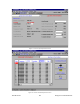
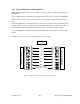
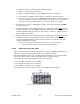
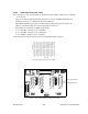
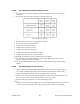
Table Of Contents
- PRODUCT OVERVIEW
- Installation
- Operating Description
- WinRIS program
- Testing and Trouble-Shooting
- Radio Programming and Adjustments
- Series I 800MHz Radio Programming
- Series I 800MHz Radio Tuning
- Series II Radio Programming
- Series II Radio Tuning
- Specifications
120 20170-201 Paragon
PD
Technical Manual
45
6.4 Series II Radio Tuning
This section covers some basic radio tuning and verification for VHF (T83x-xx-nnnn) and UHF
(T85x-xx-nnnn) Series II base station modules.
Note: Usually, this section is not done unless called for in section 6.3 “Series II - Radio Pro-
gramming” or in
Table 11
“Checklist B”.
6.4.1 Test Equipment
- Digital multimeter & probes (e.g. Fluke 77)
- 1 HP 34330A Shunt 30A (UHF only, used for transmitter current measurement)
- Digital or analog calibrated Oscilloscope & scope probes (X1, X2 selectable)
- Calibrated COM-120B (.001ppm TCXO and 30kHz IF options)
- 3 feet long double shielded N-M to BNC-M cable (RG-214 or RG-223)
- 2x 'BNC' to 'N' type adapters (e.g. Amphenol, Greenpar).
- Bird RF power meter with 150W / 50 ohm dummy load (optional)
- 1x Torx screwdriver #10
- Pozidriv screwdriver #1 & #2
- 1x Six inch adjustable wrench
- RF tuning/trimming tools.
- Extender Rail Kit for Series II chassis (T800-13-0000)
- 1x 6" coax cable N-M to BNC-M (comes with the radio to connect the exciter to the PA)
6.4.2 Receiver module (T855 & T835)
Note 1: Refer to Figure 32 (T855) and to Figure 34 (T835) for locating tuning controls.
Note 2: When the synthesizer is unlocked, the front panel green LED called "Supply" will flash
indicating that it needs re-tuning.
Warning,
The LED will also flash when the unit is in setup mode while connected to the
PGM800win program.
6.4.2.1 Initial Setup
This initial setup will be used during all receiver alignment procedures described be-
low:
1. Remove the receiver (T855 or T835) module from the Paragon
PD
rack frame
2. Remove the receiver top cover (nearest the handle).
3. Connect the Paragon
PD
Extender Rail Kit for Series II to the empty chassis receiver slot.
4. Prepare the multimeter to DC Volts.
5. Apply power to the Paragon
PD
.