
Technical Manual
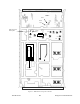
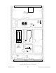
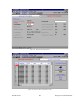
Table Of Contents
- PRODUCT OVERVIEW
- Installation
- Operating Description
- WinRIS program
- Testing and Trouble-Shooting
- Radio Programming and Adjustments
- Series I 800MHz Radio Programming
- Series I 800MHz Radio Tuning
- Series II Radio Programming
- Series II Radio Tuning
- Specifications

120 20170-201 Paragon
PD
Technical Manual
35
WARNING: Do not attempt to re-tune the IF stages (i.e. L312 to L318).
These adjustments do not need to be re-adjusted after frequency re-
programming. Touching these coils will have a direct impact on the DSP mo-
dem coefficient settings and may significantly reduce the radio performances
over data.
6.2.2.4 SINAD and Linearity Check
1. Apply the following settings to the IFR:
-
Generator mode, Output T/R
-
IFR TX frequency to match the main radio RX frequency
-
Filter set to wide band (no audio filter)
-
Select Gen2 (Modulating tone fixed to 1KHz). All other Gen must be off, except for
“wideband”.
-
Set deviation to ±3.0KHz for full channel or ±1.5KHz for half channel radios.
2. Lower the RF level to get a 12dB SINAD reading. Level must be better than -110dBm
(including cable loss).
3. Offset the IFR TX frequency 2KHz (full channel) or 1kHz (half channel) above the main
radio RX frequency, record the SINAD reading. It should remain within 1.5dB from the
on frequency SINAD reading.
4. Offset the IFR TX frequency 2KHz (full channel) or 1kHz (half channel) below the main
radio RX frequency, record the SINAD reading. It should remain within 1.5dB from the
on-frequency SINAD reading.
Note:
If one of the above requirements is not met, try to re-tune the front-end. If it is still
“failed”, contact your Dataradio technical support.
6.2.2.5 RSSI Adjustment
1. Apply an on-channel signal from the RF generator at a level of -110dBm modulated by a
1 kHz tone at a deviation of ±3kHz (full channel) or ±1.5kHz (half channel).
2. Adjust RV301 (RSSI level) to give 2.0V RSSI output when measured with a multimeter at
SK301 pin 2 or on the relevant backplane board at SK1 pin 5 (see Figure 30 for test point lo-
cation).
3. Vary the RF level and check the RSSI output voltage (Figure 28):
1) At –120 dBm: 1.2 VDC (+0.20 –0.45VDC)
2) At –90 dBm: 4.0 VDC (+0.20 –0.20 VDC)
3) At –80dBm: 5.0 VDC (+0.20 – 0.35VDC)
If the requirement cannot be reached, contact your Dataradio technical support.