
Technical Manual
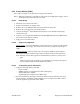
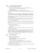
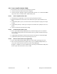
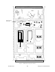
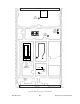
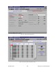
Table Of Contents
- PRODUCT OVERVIEW
- Installation
- Operating Description
- WinRIS program
- Testing and Trouble-Shooting
- Radio Programming and Adjustments
- Series I 800MHz Radio Programming
- Series I 800MHz Radio Tuning
- Series II Radio Programming
- Series II Radio Tuning
- Specifications

120 20170-201 Paragon
PD
Technical Manual
33
- The EPROM and DIP switches locations are identical in both receiver and exciter modules
(refer to Figure 21 and to Figure 22.
Figure 20 - Channel Selection via internal DIP switches
6.2 Series I 800MHz Radio Tuning
This section covers some basic tuning and verification for the 800 MHz Series I base station
modules.
Note: Usually, this section is not done unless called for in section 6.1 “Series I - Radio Pro-
gramming” or in Table 11 “Checklist B”.
6.2.1 Test Equipment
You will need the following test equipment:
- Digital multimeter and probes (e.g. Fluke 77)
- Digital or analog calibrated Oscilloscope (X1, X2 selectable)
- Calibrated COM-120B (with .001ppm TCXO and 30kHz IF options)
- 3 feet long double shielded N-M to BNC-M cable (RG-214 or RG-223)
- 2x 'BNC' to 'N' type adapters (e.g. Amphenol, Greenpar).
- Bird RF power meter with 150W / 50 ohm dummy load (optional)
- 1x Torx screwdriver #10
- Pozidriv screwdriver #1 & #2
- 1x six-inch adjustable wrench
- RF tuning/trimming tools.
- Extender Rail Kit for Series II chassis (T800-13-0000)
- 1x 6" coax cable N-M to BNC-M (provided with Paragon
PD
to connect the exciter and PA)
1
2
3
4
5
6
7
8
O
F
F
Binary Value
1
2
4
8
16
32
64
ON for 27C16 EPROM
OFF for 27C64 EPROM
(Always leave OFF)