
Technical Manual
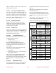
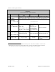
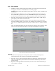
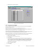
Table Of Contents
- PRODUCT OVERVIEW
- Installation
- Operating Description
- WinRIS program
- Testing and Trouble-Shooting
- Radio Programming and Adjustments
- Series I 800MHz Radio Programming
- Series I 800MHz Radio Tuning
- Series II Radio Programming
- Series II Radio Tuning
- Specifications
120 20170-201 Paragon
PD
Technical Manual
32
7. A selection box opens, in the “Device Selector:” field, type M27C64A. Move to and
choose the brand of EPROM. Press ENTER to close the selection box. The program is
now ready to configure the EPROM and the name of the device is displayed at the bot-
tom of the screen.
8. Move to and select “Device”
9. In the now opened sub-menu, move to and select “Program”.
10. Press ENTER. The program loads the binary file into the EPROM (approximately fifteen
seconds). The message “Function complete” displays until directional arrows are pressed
again. *
11. Move to and select “Buffer”
12. In the now opened sub-menu, move to and select “Clear”
13. Press ENTER. The program displays at the bottom of the screen: “All buffers cleared”
14. Press ENTER
15. Move to and select “Quit”
16. Press ENTER
17. Remove configured EPROM from the EPROM Programmer
*
If an “Error” message (and warning beep) appears during the procedure, it
normally indicates improper erasure of the EPROM. Replace it with a fresh
one and start from the beginning. The removed EPROM will need to be cy-
cled through an EPROM eraser.
6.1.5 EPROM Installation
Warning
Always use a grounding strap and wear an anti-static bracelet when working with sensi-
tive circuitry or components susceptible to static discharge or transients damage.
1. Remove power to the radio
2. Unscrew #1 Pozidriv screw on the front panel to slide out the module.
3. Unscrew the fourteen #2 Pozidriv screws on the handle side and remove cover.
4. Using a small flat-bladed screwdriver, carefully slide the blade between the EPROM
socket and the chip (IC1) itself. Gently pry the chip away from its base and remove. The
removed EPROM will need to be cycled through an EPROM eraser. Refer to Figure 21
on page 39.
5. Install the appropriate EPROM by carefully grasping the chip between thumb and index
and gently inserting it with a rocking motion in its socket until well seated.
6. Select the channel configured in the EPROM as detailed in the next section.
6.1.6 Channel Selection via DIP Switches
Channel selection is done via DIP switches inside each module.
Example: To select channel 5, the DIP switch settings are as shown in Figure 20 below.
Notes:
- For channel 1 (one), switch #1 must be OFF and switches #2 through #7 must be ON.
- Always have switch #8 set to OFF.