
Technical Manual
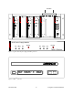
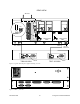
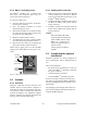
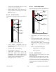
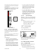
Table Of Contents
- PRODUCT OVERVIEW
- Installation
- Operating Description
- WinRIS program
- Testing and Trouble-Shooting
- Radio Programming and Adjustments
- Series I 800MHz Radio Programming
- Series I 800MHz Radio Tuning
- Series II Radio Programming
- Series II Radio Tuning
- Specifications

120 20170-201 Paragon
PD
Technical Manual
9
2.6 Checking out Normal
Operation
1- Check that power is applied.
2- Check Radio assembly lights for proper op-
eration as per section 3.1.1
3- Check for proper operation of the BDLC
PD
’s
LEDs as per section 3.2.1.2.
4- Using the WinRIS program (described in
section 4), and an in-line wattmeter, check
the forward & reflected power to confirm
antenna installations.
5- Using the WinRIS, check the RF link with a
mobile station that can be heard, by using
the WinRIS “Ping” feature. See section
4.4.5.5
If user application and a mobile station are
available, test the installation by going through a
normal sequence of transmitting and receiving
messages.
3. Operating Description
3.1 Radio Assembly
The Radio assembly component of each Paragon
product is made up of high performance synthe-
sized radio base station designed for single op-
eration. Referring to Figure 1 on page 5, the Ra-
dio Assembly’s modules are commonly installed
in a standard, 19-inch wide rack frame.
3.1.1 Front panels
The complement of modules is identical for:
Series I, (800 MHz model) and
Series II, (VHF and UHF models)*
*
800 MHz models will be available as Series II at a
future date)
• 2 Receivers
• Exciter
• Power Amplifier
• Speaker panel
• Dual Power Supply
3.1.1.1 Receiver module
The RX1 and RX2 receivers’ use identical front
panel controls and indicators. These are:
Figure 6 - Receiver module front panel
• Gating Sensitivity - sets the RF signal level
required to open the mute gate and allow
audio to pass to the speaker
1
.
• Gate LED - indicates the status of the mute
circuit. It is lit when a signal above the mute
threshold is received
1
.
• Supply LED - is lit when DC power is ap-
plied. Fast Flashes when linked with
PGM800Win. Slow Flashes indicates VCO
(synthesizer) out of lock. Unequal Flashes
indicates internal communication error.
• Line Level - Not used
• Monitor Volume - The audio output delivers
up to one watt to the speaker. Always set
1
“Gating Sensitivity” and “Gate LED” are not
functionally used except to allow listening to in-
coming receptions as a trouble-shooting aid.
Depending on the sensitivity adjustment, the
Gate LED lights and a relay can be heard on in-
coming RF signals.
Gating
Sensitivity
Gate
LED
Line
Level
Monitor
Volume
Monitor
Mute
On - Off
Receiver
®
Gating
Gate
Line
Level
Supply
Sensitivity
Monitor
Volume
Off
On
Monitor
Mute