
Technical Manual
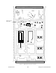
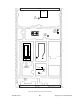
Table Of Contents
- PRODUCT OVERVIEW
- Installation
- Operating Description
- WinRIS program
- Testing and Trouble-Shooting
- Radio Programming and Adjustments
- Series I 800MHz Radio Programming
- Series I 800MHz Radio Tuning
- Series II Radio Programming
- Series II Radio Tuning
- Specifications

120 20170-201 Paragon
PD
Technical Manual
34
6.2.2 Receiver Module (T885)
Note 1: Refer to Figure 21, page 39 for locating tuning controls
Note 2: When the synthesizer is unlocked, the front panel green LED called "Supply" will be
flashing showing that it needs to be re-tuned.
6.2.2.1 Initial Setup
This initial setup will be used during each receiver alignment procedures that follow:
1. Remove the receiver (T885) module from the Paragon
PD
rack frame
2. Remove the receiver top cover (nearest the handle).
3. Connect the ParagonPD Extender Rail kit between the RX module and the empty
chassis receiver slot.
4. Set the multimeter to read DC Volts.
5. Apply power to the Paragon
PD
.
6.2.2.2 Synthesizer Alignment
Single channel: Connect the multimeter to the long lead of L1 in the VCO (this measures
the synthesizer loop voltage). Tune VCO trimmer C6 for a synthesizer loop voltage of
7V (working range is between 3V to 10V).
Multiple channels: Select the middle channel via the EPROM PCB DIP switch.
Adjust the VCO loop to 7V.
All channels should lie within the upper and lower limits of 10V and 3V respectively.
6.2.2.3 Front-End Alignment
1) IFR COM120B settings:
a) Connect a 3 feet long double shielded cable (N-M to BNC-M) between the IFR T/R
output and the receiver antenna connector.
b) Select the generator mode (GEN button) and set to the main receiver channel fre-
quency
c) Select and turnon GEN2
d) Set the FM Deviation to ±3kHz (full channel) or ±1.5kHz (half channel) using 1
kHz sine
e) Select SINAD meter
2) Monitor the SINAD by connecting an X1 scope probe to the Demod O/P test point (close
to PL103 in the first section from the module front panel) or on the relevant backplane
board at SK1 pin 6 (see Figure 30 for test point location).
3) Adjust the helical resonators #H1 to #H3 for best SINAD.
4) Continually decrease the RF level to reach 12dB SINAD, then re-do steps 3) and 4)
again. (minimum requirement to reach is 12 dB SINAD for –110 dBm)
5) Perform the SINAD linearity tests described in the next paragraphs below. If it fails to
pass the requirement, contact your Dataradio technical support.