
Technical Manual
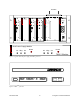
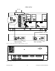
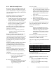
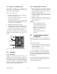
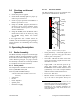
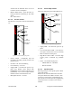
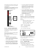
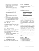
Table Of Contents
- PRODUCT OVERVIEW
- Installation
- Operating Description
- WinRIS program
- Testing and Trouble-Shooting
- Radio Programming and Adjustments
- Series I 800MHz Radio Programming
- Series I 800MHz Radio Tuning
- Series II Radio Programming
- Series II Radio Tuning
- Specifications

120 20170-201 Paragon
PD
Technical Manual
10
volume knob to minimum when not in use
to reduce current consumption.
• Monitor Mute Switch - opens the mute, al-
lowing continuous monitoring of the audio
signal.
On = audio muted
3.1.1.2 Exciter module
The Exciter’s front panel controls and indicators
are:
Figure 7 - Exciter module, front panel
• Carrier Switch - momentarily keys the
transmitter ON while pressed (used for test
purposes only).
• On LED - is lit when transmitting
• Line Sensitivity – not used.
• Supply LED - is lit when DC power is ap-
plied. Fast Flashes when linked with
PGM800Win. Slow Flashes indicates VCO
(synthesizer) out of lock. Unequal Flashes
indicates internal communication error.
• Microphone Socket – not used.
3.1.1.3 Power Amp module
The Power Amp front panel and indicators are:
Figure 8 - Power Amp module, front panel
• Supply LED - is lit when DC power is ap-
plied.
• Low Forward Power LED - is lit when for-
ward power is below the level set, normally
80% of nominal forward power.
• High Reverse Power LED - is lit when high
reverse power is detected (e.g. VSWR=
3:1).
• Power - sets the PA output power:
- VHF & UHF: 20 – 100 Watts
- 800: 20-70 Watts
3.1.1.4 Speaker panel
Referring to Figure 9, the speaker panel is fitted
with a 4Ω speaker.
Both series of radio assemblies share the same
front panel fitted with an RJ11 connector. This
connector is used to allow programming the ra-
dio from the front of the unit via a programming
lead. This feature is exclusive to the Series II
modules.
Carrier
Switch
On
LED
Supply
LED
Line
Sensitivity
Microphone
Socket
®
Exciter
Carrier
On
Line
Sensi tivity
Supply
Microphone
®
Power Am plifier
Low Forward Power
Supply
High Reverse Power
Pow er
Supply
LED
Low Forward
Power LED
High Reverse
Power LED
Power
Adjustment