
User's Manual
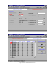
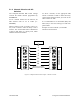
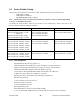
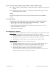

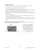
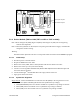
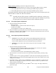
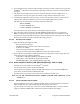
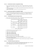
Table Of Contents
- PRODUCT OVERVIEW
- Installation
- Operating Description
- Trouble-Shooting and Testing
- Radio Programming and Adjustments
- Series II Radio Programming
- Series II Radio Tuning
- S
- Specifications

120 20170-302 Paragon
PD
Technical Manual
32
Figure 24 - T800-50-0001 Backplane
5.2.3 Exciter Module (T881-xx-0200,T857-xx-0250 or T837-xx-0200)
Note 1: Refer to Figure 28 (T881), Figure 30 (T857) and to Figure 32 (T837) for locating tuning
controls and components.
Note 2: When the synthesizer is unlocked, the front panel green LED called "Supply" will flash indi-
cating that it needs re-tuning.
Warning:
The LED will also flash when the unit is in setup mode while connected to the PGM800win program.
5.2.3.1 Initial Setup
1. Shut down power to the base station.
2. Prepare the Multimeter to DC Volts.
3. Remove the exciter (T881, T857 or T837) module from the base station rack frame.
4. Remove the exciter top cover (nearest the handle).
5. Connect a 3 feet long double shielded cable (N-M to BNC-M) between the IFR T/R output and
the exciter antenna connector.
6. Connect the Paragon
PD
Extender Rail Kit to the empty chassis exciter slot.
7. Apply power to the base station.
5.2.3.2 Synthesizer Alignment
Single channel: Connect the Multimeter to either side of L309 (T881) or the long lead of L1 in the
VCO (T857 and T835) (this measures the synthesizer loop voltage).
1. T881 (800/900 MHz) Tune VCO trimmer CV300 for a synthesizer loop voltage of 10V DC.
2. T857 (UHF) Tune VCO trimmer C6 for a synthesizer loop voltage of 10V DC.
3. T837 (VHF). Tune VCO trimmer CV1 for a synthesizer loop voltage of 9VDC.
1
2
3
4
5
6
7
8
O
F
F
1
2
3
4
5
6
7
8
O
F
F
SW2
SW1
RX
CH
AN
EL
SW
ITC
H
TX
CH
AN
EL
SW
ITC
H
OFF
ON
OFF
ON
PL1
SK1
1
5
6
RSSI ouput SK1 pin 5
RX-Audio1 SK1 pin 6
5
6
RX-Audio1 SK1 pin 6
RSSI ouput SK1 pin 5