
User's Manual
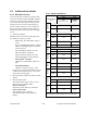
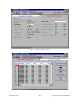
Table Of Contents
- PRODUCT OVERVIEW
- Installation
- Operating Description
- Trouble-Shooting and Testing
- Radio Programming and Adjustments
- Series II Radio Programming
- Series II Radio Tuning
- S
- Specifications

120 20170-302 Paragon
PD
Technical Manual
21
Table 9 - Checklist B (General)
CHECKLIST B (Paragon
PD
)
General Check out (part1 of 2)
Paragon
PD
units are set and characterized at the factory to optimize performances.
It is not recommended to try readjusting units unless it is really required.
Misadjusting a unit may result in significant performance losses.
The proposed adjustments in the "IF NOT?" column below, should be tried ONLY if system data
performance degradation is noticed combined with out-of-tolerance items.
Step ACTION
Expected Results at 25°
°°
°C
MEASURE WITH IF NOT?
1
Normal Power-up
Sequence
BDLC
PD
beeps once, all LEDs come ON for about four seconds, the green LEDs
then flash in a “ripple” pattern for close to two seconds. All LEDs go OFF except the
CK that should flash 6 to 8 times per second. For functions, see section 3.2.1.5
2
Connect and save
unit config
Press WinRIS Get
button
as per WinRIS Help content
3
Transmitter Output
Power
Press TX ON (Unmod)
VHF/UHF: 20 - 100 watts
800 MHz: 20 - 70 watts
900 MHz: 65 - 100 watts
+10%, -10%
Service monitor set
to read power
or
150W in-line watt-
meter installed as
close as possible
to the unit antenna
connector.
Adjust “Power” on the front
panel of the “Power Amp”
( see Figure 8)
4
Transmitter
Reflected Power
Press TXON (Unmod)
< 5% of forward power or
as specified by System
Engineering.
10 W in-line
wattmeter
Check for bad connections,
damaged coax cable, etc.
5
Carrier Frequency
Error
Press TX (Unmod)
< ±300 Hz
Service monitor set
to read frequency
error
Adjust TCXO (IC700)
(see inside Exciter module at,
Figure 28 (800), Figure 30
(UHF), Figure 32 (VHF) )
6
TX Deviation (KHz)
Press
TX (Unmod)
Carrier will be modu-
lated with a 1 kHz tone.
Refer to "Figure 16 - Carrier
deviations for Tone or Data
Modulation" per bit rates
Tolerance is +5%, -10%
for all bit rates.
Service monitor set
to read deviation.
(IF filter set to Mid
or 30 kHz position)
Adjust according to Appendix 1
- ParagonPD Deviation adjust
on page 44
7
Low Frequency
Balance
Initiate a
TX Random data
test
via BDLC
PD
’s PF1
(See Table 3)
a) Record deviation level
read from step 6
b) Record deviation read
from TX Random test
c) Difference between
a) and b) should be:
< 600 Hz (DGMSK)
< 1.5 kHz (xSR4FSK, HC)
< 2.0 kHz (xSR4FSK,
FC/NPSPAC)
Service monitor set
to read deviation
(IF filter set to Mid
or 30 kHz position,
all audio filtering
disabled )
Refer to
Section 5.2.3.4