
User's Manual
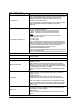
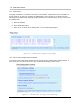
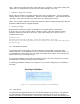
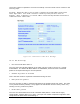
Table Of Contents
- 1 VIPER OVERVIEW
- 2 SYSTEM ARCHITECTURE AND NETWORK PLANNING
- 3 DATARADIO VIPER QUICK START
- 4 VIPER WEB MANAGEMENT
- 5 UNIT STATUS
- 6 SETUP (BASIC)
- 7 SETUP (ADVANCED)
- 7.1 RF OPTIMIZATIONS
- 7.2 IP SERVICES
- 7.3 IP ADDRESSING
- 7.4 IP OPTIMIZATION
- 7.5 IP ROUTING (TABLE/ENTRIES)
- 7.6 TIME SOURCE
- 7.7 ALARM REPORTING
- 7.8 USER SETTINGS
- 8 SECURITY
- 9 STATISTICS
- 10 MAINTENANCE
- 11 NEIGHBOR MANAGEMENT
- 12 NETWORK OPTIMIZATION
- 13 UPGRADING YOUR FIRMWARE
- VIPER SPECIFICATIONS
- PRODUCT WARRANTY
- DEFINITIONS

001-5008-000(Rev8) Page 93
Note: Both the IP and port filte ct which packets are sent via
t .
Example 2
r information are used to sele
he VPN tunnel
I e source netmask is 255.255.255.0, so messages originating from source
I passed
t t “Block non-VPN
T
The destination IP address is 0.0.0.0 and the destination port range is 0 to 0. So messages
destined to any IP address and any destination port will be passed through the VPN tunnel.
n this example th
P addresses: 172.30.51.1-172.30.51.254 and from ports: 5555-6000 will be
hrough the VPN tunnel. All other messages will be blocked (assuming tha
raffic” is enabled).