
User's Manual

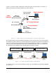
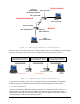
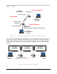
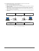
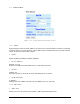
Table Of Contents
- 1 VIPER OVERVIEW
- 2 SYSTEM ARCHITECTURE AND NETWORK PLANNING
- 3 DATARADIO VIPER QUICK START
- 4 VIPER WEB MANAGEMENT
- 5 UNIT STATUS
- 6 SETUP (BASIC)
- 7 SETUP (ADVANCED)
- 7.1 RF OPTIMIZATIONS
- 7.2 IP SERVICES
- 7.3 IP ADDRESSING
- 7.4 IP OPTIMIZATION
- 7.5 IP ROUTING (TABLE/ENTRIES)
- 7.6 TIME SOURCE
- 7.7 ALARM REPORTING
- 7.8 USER SETTINGS
- 8 SECURITY
- 9 STATISTICS
- 10 MAINTENANCE
- 11 NEIGHBOR MANAGEMENT
- 12 NETWORK OPTIMIZATION
- 13 UPGRADING YOUR FIRMWARE
- VIPER SPECIFICATIONS
- PRODUCT WARRANTY
- DEFINITIONS

In the example below (Figure - 7.23) the following events occur in this order:
1) Host A sends TCP data packet to Viper A.
2) Viper A transmits packet over the air to Viper B.
4) Viper A hears an RF acknowledgement from Viper B and generates a TCP ACK to
ives the original TCP data packet and generates a TCP
ACK to send back over the network.
t does not send it over the air saving bandwidth on
ample
3) Viper B immediately responds with an RF acknowledgment and sends the TCP data
packet to Host B.
send to Host A. Host B rece
5) Viper B receives the TCP ACK bu
the Airlink
(1) TCP Packet over Ethernet
(2) TCP Packet over Airlink
(3) TCP Packet over Ethernet
001-5008-000(Rev8) Page 78
Host A
Host B
V
iper
A
TCP Proxy Enabled
V
iper B
TCP Proxy Enabled
(4) When Viper A hears RF ACK it
generates a TCP ACK and sends it
to Host
(3) RF ACK over Airlink
(5) TCP ACK is not transmitted
(4) Host B generates TCP ACK.
A
Figure - 7.23 TCP Proxy Ex