
User's Manual

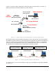
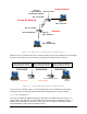
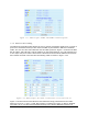
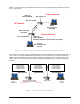
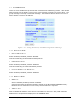
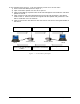
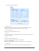
Table Of Contents
- 1 VIPER OVERVIEW
- 2 SYSTEM ARCHITECTURE AND NETWORK PLANNING
- 3 DATARADIO VIPER QUICK START
- 4 VIPER WEB MANAGEMENT
- 5 UNIT STATUS
- 6 SETUP (BASIC)
- 7 SETUP (ADVANCED)
- 7.1 RF OPTIMIZATIONS
- 7.2 IP SERVICES
- 7.3 IP ADDRESSING
- 7.4 IP OPTIMIZATION
- 7.5 IP ROUTING (TABLE/ENTRIES)
- 7.6 TIME SOURCE
- 7.7 ALARM REPORTING
- 7.8 USER SETTINGS
- 8 SECURITY
- 9 STATISTICS
- 10 MAINTENANCE
- 11 NEIGHBOR MANAGEMENT
- 12 NETWORK OPTIMIZATION
- 13 UPGRADING YOUR FIRMWARE
- VIPER SPECIFICATIONS
- PRODUCT WARRANTY
- DEFINITIONS

Figure 7.13 shows a Viper configuration protecting Viper (2) RF interface and Viper (1)
Ethernet interface from hosts located on a public network.
Eth: 172.31.5.1
RF: 10.0.14.203
RF: 10.0.14.186
Eth: 192.168.205.1
Host 2
Eth: 172.31.5.2
Viper (1)
(NAT enabled,
Ethernet Interface is private)
Viper (2)
(NAT enabled,
RF interface private)
Private Network
Host 1
Eth: 192.168.205.2
Public Network
Pubic
Network
RF Private Network
Figure 7.13 - NAT on Viper: Private RF interface and Private Eth interface
An IP packet whose source IP address originates from the RF network and is sent towards
the Ethernet network will have its source IP address replaced by the Ethernet IP address of
Viper (2). Notice in this configuration the Ethernet IP address for Viper (1) is considered
private and the RF IP address for Viper (2) is considered private.
Figure 7.14 shows how
the packets will be modified as the packets pass through the network.
Packet (1)
Source Address 192.168.205.2
D
est
in
at
i
o
n A
dd
r
ess
172.
3
1.
5
.2
Packet (1)
Source Address 10.0.14.203
D
est
in
at
i
o
n A
dd
r
ess
172.
3
1.
5
.2
Packet (1)
Source Address 172.31.5.1
D
est
in
at
i
o
n A
dd
r
ess
172.
3
1.
5
.2
Host 1
192.168.205.2
Host 2
172.31.5.2
V
iper 1
NAT enabled, Eth is private
V
iper 2
NAT enabled, RF is private
Private Network
Private RF Network
Public Network
Figure 7.14 - Packet flow Private Eth and RF interface
In example Figure 7.15, the RF interface of Viper (2) is considered private. NAT is disabled
for Viper (1).
001-5008-000(Rev8) Page 72