
User's Manual
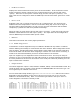
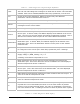

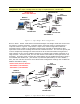
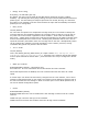

Table Of Contents
- 1 VIPER OVERVIEW
- 2 SYSTEM ARCHITECTURE AND NETWORK PLANNING
- 3 DATARADIO VIPER QUICK START
- 4 VIPER WEB MANAGEMENT
- 5 UNIT STATUS
- 6 SETUP (BASIC)
- 7 SETUP (ADVANCED)
- 7.1 RF OPTIMIZATIONS
- 7.2 IP SERVICES
- 7.3 IP ADDRESSING
- 7.4 IP OPTIMIZATION
- 7.5 IP ROUTING (TABLE/ENTRIES)
- 7.6 TIME SOURCE
- 7.7 ALARM REPORTING
- 7.8 USER SETTINGS
- 8 SECURITY
- 9 STATISTICS
- 10 MAINTENANCE
- 11 NEIGHBOR MANAGEMENT
- 12 NETWORK OPTIMIZATION
- 13 UPGRADING YOUR FIRMWARE
- VIPER SPECIFICATIONS
- PRODUCT WARRANTY
- DEFINITIONS

001-5008-000(Rev8) Page 47
Note: This configuration can be substituted for a traditional serial RS232 radio system
configuration. The Viper in bridge mode is a drop in replacement for a serial radio.
Viper
192.168.205.1
Viper
192.168.205.3
PLC
192.168.205.
HMI/PLC
192.168.205.10
HMI/PLC
192.168.205.1
PLC
192.168.205.30
PLC
192.168.205.20
Viper
192.168.205.2
Viper
192.168.205.4
Bridge Mode
Subnet 192.168.205.0
Figure 6.2 - Viper Bridge Mode Configuration.
Router Mode: Router mode offers several advantages over Bridge mode and can be used
for simple or complex networks. In Router mode, each Viper must be configured for a
unique IP subnet. Figure 6.3 represents a Viper router mode configuration. Ethernet
messages will be routed to the intended recipient Viper and will be discarded by other
Vipers that overhear the message that was not intended for them. The user can specify the
route a multiple hop message will travel and thus can channel the traffic throughout the
Viper network to give a more reliable connection or perhaps relieve traffic congestion on a
large network. In Router mode, the user has access to the RSSI for each Viper that is one
hop away. In Router mode, several retry mechanisms can be enabled which often yields a
more stable and reliable link. (See section 12, Network Optimization, for more details.)
Also, the user will have access to more advanced IP configuration settings such as Network
Address Translation (NAT).
Viper
192.168.205.1
Viper
192.168.207.1
Viper
192.168.208.1
PLC
192.168.208.2
HMI/PLC
192.168.205.2
HMI/PLC
192.168.205.100
PLC
192.168.207.2
PLC
192.168.206.2
Viper
192.168.206.1
Router Mode, Different Subnets
192.168.205.0, 192.168.206.0,
192.168.207.0, 192.168.208.0
Figure 6.3 - Viper Router Mode Configuration