
User's Manual
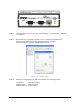
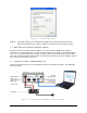
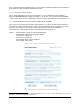
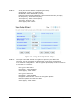
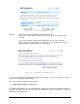
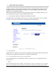
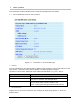
Table Of Contents
- 1 VIPER OVERVIEW
- 2 SYSTEM ARCHITECTURE AND NETWORK PLANNING
- 3 DATARADIO VIPER QUICK START
- 4 VIPER WEB MANAGEMENT
- 5 UNIT STATUS
- 6 SETUP (BASIC)
- 7 SETUP (ADVANCED)
- 7.1 RF OPTIMIZATIONS
- 7.2 IP SERVICES
- 7.3 IP ADDRESSING
- 7.4 IP OPTIMIZATION
- 7.5 IP ROUTING (TABLE/ENTRIES)
- 7.6 TIME SOURCE
- 7.7 ALARM REPORTING
- 7.8 USER SETTINGS
- 8 SECURITY
- 9 STATISTICS
- 10 MAINTENANCE
- 11 NEIGHBOR MANAGEMENT
- 12 NETWORK OPTIMIZATION
- 13 UPGRADING YOUR FIRMWARE
- VIPER SPECIFICATIONS
- PRODUCT WARRANTY
- DEFINITIONS

001-5008-000(Rev8) Page 36
Figure 3.9 - Using the Setup Wizard: Step 4
STEP 5: Click “Done” before completing the remaining steps.
Note: If the “Done” button is not clicked on new units, the units will not
transmit.
To save the network configuration parameters of your Viper, click the
“Save Config” command button. You will see a green success icon on the
bottom left of the page when save is complete.
Figure 3.10 - Using the Setup Wizard: Step 5
If you have changed any parameters marked with a yellow “!” icon, you must cycle power to
the unit using the “Reset Unit” button.
Your unit is now functioning in Bridge Mode.
3.7 CHECK FOR NORMAL OPERATION
To simulate data traffic over the radio network, connect a PC or LAN to the Ethernet port of
the Viper and PING each unit in the network multiple times. Refer to section 10.1 on how to
utilize the Viper PING utility.