
User's Manual
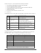
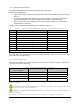
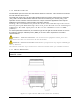
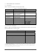
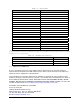

Table Of Contents
- 1 VIPER OVERVIEW
- 2 SYSTEM ARCHITECTURE AND NETWORK PLANNING
- 3 DATARADIO VIPER QUICK START
- 4 VIPER WEB MANAGEMENT
- 5 UNIT STATUS
- 6 SETUP (BASIC)
- 7 SETUP (ADVANCED)
- 7.1 RF OPTIMIZATIONS
- 7.2 IP SERVICES
- 7.3 IP ADDRESSING
- 7.4 IP OPTIMIZATION
- 7.5 IP ROUTING (TABLE/ENTRIES)
- 7.6 TIME SOURCE
- 7.7 ALARM REPORTING
- 7.8 USER SETTINGS
- 8 SECURITY
- 9 STATISTICS
- 10 MAINTENANCE
- 11 NEIGHBOR MANAGEMENT
- 12 NETWORK OPTIMIZATION
- 13 UPGRADING YOUR FIRMWARE
- VIPER SPECIFICATIONS
- PRODUCT WARRANTY
- DEFINITIONS

1.3.4 SETUP and COM Ports
The SETUP and COM serial connections are DE-9F RS-232 ports.
Serial port considerations:
• Viper radio modem SETUP and COM ports are Data Communication Equipment (DCE)
devices
• In general, equipment connected to the Viper’s SETUP / COM serial port is Data
Terminal Equipment (DTE) and a straight-through cable is recommended.
Note: If a DCE device is connected to the Viper SETUP / COM port, a null modem
cable/adapter is required.
The pin-out for the SETUP and COM ports are shown in Table 1-3
Table 1-3- Pin-out for DCE SETUP and COM port, 9 Contact DE-9 Connector
Contact EIA-232F Function Signal Direction
1 DCD
(1)
DTE ← DCE
2 RXD
DTE ← DCE
3 TXD
DTE → DCE
4 DTR
DTE → DCE
5 GND DTE --- DCE
6 DSR
(2)
DTE ← DCE
7 RTS
(1)
DTE → DCE
8 CTS
(1)
DTE ← DCE
9 RING
(3)
DTE --- DCE
(1) Programmable. (2) Always asserted. (3) For future use.
The DCD, DTR, RTS and CTS control lines are programmable. Refer to section 6.4 for serial
port control line configurations.
1.3.5 Power Connector
The Viper is supplied with a right-angle power connector (10-30 VDC). Table 1-4 shows the
pin-out of the power connector.
Table 1-4 - Pin-out of the power connector
Contact #
(Left to Right)
Color Description
4 Fan Power Output (5V)
3 Black Ground
2 Red Positive (10-30) VDC
1 White Enable
Note: The White Enable line must be tied to the red positive lead of the connector for the
Viper to function.
WARNING – EXPLOSION HAZARD- Do not disconnect unless power has been removed
or the area is known to be non-hazardous
WARNING -EXPLOSION HAZARD-Substitution of components may impair suitability for
Class I, Division 2.
The unit is to be powered with a Listed Class 2 or LPS power supply or equivalent.
001-5008-000(Rev8) Page 13