
User's Manual

#9 Viper_SC_Manual_001-5008-000_Rev12d.docx | Page 4
Contact
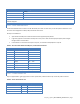
10 Base-T Signal
6
RXN(1)
7
SPARE
8
SPARE
SHELL
Shield
(1) The name shows the default function. Given the Auto-MDIX capability of the Ethernet transceiver, TX and RX function
could be swapped.
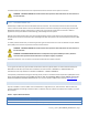
1.3.3.2 SETUP AND COM PORTS
The SETUP and COM serial connections are DE-9F RS-232 ports. Refer to Table 3 for pin out descriptions and Section 4.3.4
for control line configuration of DCD, DTR, RTS and CTS control lines.
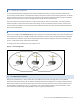
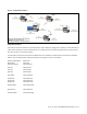
Serial port considerations:
Viper SETUP and COM ports are Data Communication Equipment (DCE) devices
In general, equipment connected to the Viper SC’s serial ports is Data Terminal Equipment (DTE) and a straight-
through cable is recommended.
If a DCE device is connected to the Viper serial ports, a null modem cable/adapter is required.
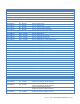
Table 3 – Pin-out for DCE SETUP and COM port, 9 Contact DE-9 Connector
Contact
EIA-232F Function
Signal Direction
1
DCD(1)
DTE ← DCE
2
RXD
DTE ← DCE
3
TXD
DTE → DCE
4
DTR
DTE → DCE
5
GND
DTE --- DCE
6
DSR(2)
DTE ← DCE
7
RTS(1)
DTE → DCE
8
CTS(1)
DTE ← DCE
9
RING (3)
DTE --- DCE
(1) Programmable (2) Always asserted (3) For future use
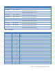
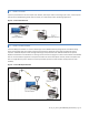
1.3.3.3 POWER CONNECTOR
Viper is supplied with a right-angle power connector (10-30 VDC). Table 4 shows the pin-out of the power connector.
Table 4 – Power Connector Pin-out
Contact (Left to Right)
Color
Description
4
Fan Power Output (5V)
3
Black
Ground
2
Red
Positive (10-30) VDC
1
White
Enable