
User's Manual

#9 Viper_SC_Manual_001-5008-000_Rev12d.docx | Page 3
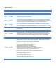
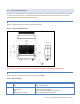
LED
Color
Definition
ACT
Blinking Green
Off
Ethernet activity detected on PHY link (RJ45)
No Ethernet activity on PHY link (RJ45)
Lnk
Green
Off
Ethernet connection established (RJ45)
No Ethernet connection (RJ45)
Rx/Tx
Green
Red
Receiving data
Transmitting data
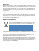
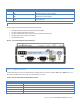
1.3.3 FRONT PANEL
Shown in Figure 2, the front panel has the following connections:
(1) RJ-45 LAN 10 BaseT Ethernet connection with Auto-MDIX
(1) 50-ohm TNC female Antenna connector
(1) 50-ohm SMA female receive antenna connector (Dual-Port models only)
(1) Right-angle power connector (10-30 VDC)
(2) DE-9F RS-232 ports
Figure 2 – Front Panel (Dual Port Viper-200 Shown)
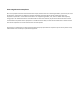
1.3.3.1 ETHERNET LAN PORT
The Ethernet LAN port is an RJ-45 receptacle with a 10 BaseT Ethernet connection and Auto-MDIX. Refer Table 2 for pin out
descriptions and Section 4.6.1 to configure the LAN settings for this port.
Table 2 – Pin-out for IEEE-802.3 RJ-45 Receptacle Contacts
Contact
10 Base-T Signal
1
TXP(1)
2
TXN(1)
3
RXP(1)
4
SPARE
5
SPARE