
User's Manual

001-5008-000 rev5_2.doc Page 30
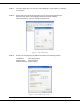
STEP 4: Click OK to apply your changes and complete the connection process. Some
Operating systems may require a reboot to complete the connection process.
3.4 MEASURE AND CONNECT PRIMARY POWER
Primary power for the ViPR must be within 10-30 VDC and be capable of providing a
minimum of 10 watt supply for Tx @ 1W, 40 watt supply for Tx @ 5W, or 60 watt supply for
Tx @ 10 W. (In ViPR Demo Kits, a power connector with screw-terminals is provided with
each unit.) Observe proper polarity when connecting the cables to the Power Supply. (White
wire must be connected to red wire.)
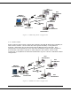
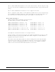
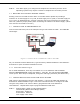
3.5 CONNECT VIPR TO PROGRAMMING PC
Connect a PC’s Ethernet port to the LAN port using a CAT 5 Ethernet cable. The LINK LED
should light.
Figure 3.6 Connect Power and Ethernet cable to the ViPR.
On your Internet browser address line, type the factory-default IP address: 192.168.205.1.
Press Enter to open the Network Password screen.
3.5.1 Initial Installation Login
For an initial installation, enter any User Name of 1 to 15 characters and the default
Password ADMINISTRATOR (upper case letters). Click OK. The web interface WELCOME
screen opens. Once setup is completed, change the ViPR login password (See Section 8.1).
3.6 CONFIGURE YOUR VIPR USING THE SETUP WIZARD
ViPR units are programmed using the web interface. Log into the ViPR web interface as
described in Initial Installation Login. Follow the instructions below to configure the ViPR
using the setup wizard. All units are factory programmed with an IP address of
192.168.205.1. Repeat these steps to program additional ViPR units.
STEP 1: Station Name: Assign a unique Station Name
IP Forwarding Mode: Select Bridge (Mode)
Relay Point: Select No
Access Point: Select No
Click “Apply” Click “Next”