
User's Manual

001-5008-000 rev5_2.doc Page 28
3
3
D
D
A
A
T
T
A
A
R
R
A
A
D
D
I
I
O
O
V
V
I
I
P
P
R
R
Q
Q
U
U
I
I
C
C
K
K
S
S
T
T
A
A
R
R
T
T
3.1 SETUP AND CONFIGURATION
It is easy to set up a ViPR network to verify basic unit operation and experiment with
network designs and configurations.
It is important to use a network IP subnet address different from others currently in use in
your test area. This will eliminate unnecessary disruption of traffic on the existing network
while you become familiar with the ViPR.
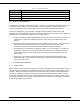
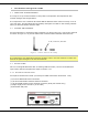
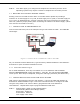
3.2 INSTALL THE ANTENNA
An RX/TX antenna is required for basic operation. For demo units only, connect the antenna
as shown in Figure 3.1 to provide stable radio communications between demo devices.
Figure 3.1 -Demo Antenna Assembly
Note:
It is important to use attenuation between all demo units in the test network to reduce the
amount of signal strength in the test environment.
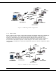
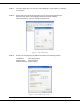
3.3 PC LAN SETUP
On a PC running MS-Windows with an existing LAN connection, connect to the Ethernet
input of the ViPR and complete the steps in section 3.3.1
3.3.1 Front Panel Connections
Front panel connections include: (For Dual-port ViPR connections see Section 1.3.6.)
(1) RJ-45 10 BaseT Ethernet Connection
(1) 50-ohm TNC female transmit antenna connector
(1) 50-ohm SMA female receive antenna connector (Dual-port models only)
(1) Right-angle power connector (10-30 VDC)
(2) DE-9F RS-232 ports
Figure 3.2 Front Panel (Standard model shown)
20 dB, 5 watt max, attenuator