
User's Manual

001-5008-000 rev5_2.doc Page 11
1.3.4 SETUP and COM Ports
The SETUP and COM serial connections are DE-9F RS-232 ports.
Serial port considerations:
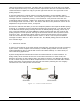
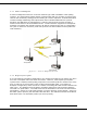
• ViPR radio modem SETUP and COM ports are Data Communication Equipment (DCE)
devices
• In general, equipment connected to the ViPR’s SETUP / COM serial port is Data
Terminal Equipment (DTE) and a straight-through cable is recommended.
Note: If a DCE device is connected to the ViPR SETUP / COM port, a null modem
cable/adapter is required.
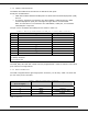
The pin-out for the SETUP and COM ports are shown in Table 1.3.
Table 1.3 Pin-out for DCE SETUP and COM port, 9 Contact DE-9 Connector
Contact EIA-232F Function Signal Direction
1 DCD
(1)
DTE ← DCE
2 RXD
DTE ← DCE
3 TXD
DTE → DCE
4 DTR
DTE → DCE
5 GND DTE --- DCE
6 DSR
(2)
DTE ← DCE
7 RTS
(1)
DTE → DCE
8 CTS
(1)
DTE ← DCE
9 RING
(3)
DTE --- DCE
(1) Programmable.
(2) Always asserted
(3) For future use
The DCD, DTR, RTS and CTS control lines are programmable. Refer to section 6.4 for serial
port control line configurations.
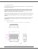
1.3.5 Power Connector
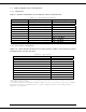
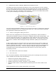
The ViPR is supplied with a right-angle power connector (10-30 VDC). Table 1.4 shows the
pin-out of the power connector.
Table 1.4 Pin-out of the power connector
Contact #
(Left to Right)
Color Description
4 Fan Power Output (5V)
3 Black Ground
2 Red Positive (10-30) VDC
1 White Enable
Note: The White Enable line must be tied to the red positive lead of the connector for the
ViPR to function.