ViPR™ Narrowband IP Modem/Router User Manual PN 001-5008-000 Rev 5 Revised July 2009
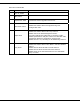
REVISION HISTORY REV DATE 0 Jan 11, 2008 1 May 2008 2 September 2008 3 4 5 December 2008 April 2009 July 2009 REVISION DETAILS Initial Release as 001-5008-000. Update Dual Port ViPR information. Added information about SNMP. Updated Firmware Upgrade instructions. Added information about TCP Client Server Mode. Added information about Saving/Restoring User Configuration files. Added information about V1.5 ViPR code release. Added information about TCP Proxy Feature.
IMPORTANT NOTICE Because of the nature of wireless communication, transmission and reception of data can never be guaranteed. Data may be delayed, corrupted (i.e., have errors), or be totally lost. Significant delays or losses of data are rare when wireless devices such as the ViPR are used in a normal manner with a well-constructed network.
TABLE OF CONTENTS 1 VIPR OVERVIEW.......................................................................................................................................................8 1.1 General Description............................................................................................................................................8 1.2 Operational Characteristics..............................................................................................................................
3.3 PC LAN Setup...................................................................................................................................................12 3.3.1 Front Panel Connections.............................................................................................................................12 3.4 Measure and Connect Primary Power............................................................................................................12 3.5 Connect ViPR to Programming PC ....
7.7 Alarm Reporting...............................................................................................................................................12 7.7.1 Forward Power Alarm & Notification ........................................................................................................12 7.7.2 Reverse Power Alarm & Notification.........................................................................................................12 7.7.3 PA Power Alarm & Notification................
12.2.1 12.2.2 12.2.3 13 Use Router Mode with RF Acknowledgements Enabled............................................................................12 Reduce RF Network Bit Rate .....................................................................................................................12 Increase OIP and MAC Retries Limit.........................................................................................................12 UPGRADING YOUR FIRMWARE...............................................
1 VIPR OVERVIEW This document provides information required for the operation and verification of the Dataradio ViPR Narrowband IP Modem/Router. The information in this manual makes the assumption the user’s PC has an NIC (Network Interface Card) with TCP/IP implemented. Setup requires the knowledge and authorization to modify the TCP/IP settings for the NIC. Changing or installing new IP addresses in a network can cause serious network problems.
These features provide system benefits that give users: Rugged Packaging. ViPR is housed in a compact and rugged cast aluminum case. Built for industrial applications in a variety of environments, ViPR operates over an extended temperature range and provides worry-free operation in the roughest environments. Simple Installation. Basic installation typically utilizes an omni-directional antenna at the master station or Relay Point and a directional antenna at each remote site not a Relay Point.
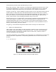
As shown in Figure 1.1, the front panel has the following connections: (1) RJ-45 LAN 10 BaseT Ethernet connection with Auto-MDIX (1) 50-ohm TNC female Antenna connector (1) 50-ohm SMA female receive antenna connector (Dual-Port models only) (1) Right-angle power connector (10-30 VDC) (2) DE-9F RS-232 ports For Dual-port ViPR connections, see Section 1.3.6. 1.3.2 LED Panel The LED panel has five Tri-Color LEDs. The functionality of each LED is shown in Table 1.1. Table 1.
1.3.4 SETUP and COM Ports The SETUP and COM serial connections are DE-9F RS-232 ports. Serial port considerations: • ViPR radio modem SETUP and COM ports are Data Communication Equipment (DCE) devices • In general, equipment connected to the ViPR’s SETUP / COM serial port is Data Terminal Equipment (DTE) and a straight-through cable is recommended. Note: If a DCE device is connected to the ViPR SETUP / COM port, a null modem cable/adapter is required.
1.3.6 Antenna Connector The standard ViPR has a 50-ohm TNC female antenna connector. This connection functions for both transmit and receive. The Dual-Port ViPR has a 50-ohm TNC female antenna connector functioning for transmit (only) and a 50-ohm SMA female antenna connector functioning for receive (only). The separate receive antenna connector allows for unique customer applications that require additional receive filtering, external PA(s) and other options.
1.4 PART NUMBERS AND AVAILABILITY 1.4.1 ViPR Radio Table 1.5 provides a breakdown of the ViPR part number 140-50X8-Y0Z. Model Number 140-5018-500 140-5028-502 140-5048-300 140-5048-500 140-5098-500 Table 1.5 - Part Number Breakdown Frequency Range Description Standard VHF ViPR 136 - 174 MHz 215 – 240 MHz Standard VHF ViPR 200 406.
Table 1.7 Antenna Kits ITEM Antenna Antenna Antenna Antenna Antenna Antenna Antenna Antenna Antenna Antenna Antenna Antenna Antenna Antenna Antenna Antenna Antenna Antenna Antenna Antenna Kit*: Kit*: Kit*: Kit*: Kit*: Kit*: Kit*: Kit*: Kit*: Kit*: Kit*: Kit*: Kit*: Kit*: Kit*: Kit*: Kit*: Kit*: Kit*: Kit*: 138-143 138-143 143-148 143-138 148-152 148-152 152-157 152-157 157-163 157-163 163-169 163-169 169-174 169-174 216-222 216-222 450-470 450-470 890-960 890-960 MHz 6.5 dBd MHz 9.5 dBd MHz 6.
FACTORY AND TECHNICAL SUPPORT M-F 7:30-4:30 CST CalAmp Wireless DataCom 299 Johnson Ave., Ste 110, Waseca, MN 56093 Tel 507.833.8819; Fax 507.833.6758 Email imcsupport@calamp.com 1.6 RMA REQUEST When returning a product, mark the RMA clearly on the outside of the package. Include a complete description of the problem and the name and telephone number of a contact person. RETURN REQUESTS WILL NOT BE PROCESSED WITHOUT THIS INFORMATION. Contact Customer Service: 299 Johnson Ave.
2 SYSTEM ARCHITECTURE AND NETWORK PLANNING This section briefly discusses network architecture (including basic network types), interfacing modems and DTE, data protocols for efficient channel operation, addressing, and repeaters. ViPR is designed to replace wire lines in SCADA, telemetry and control applications. The Ethernet and RS-232 serial port allows direct connection to Programmable Logic Controllers (PLCs) or Remote Terminal Units (RTUs).
capture the airwaves to transmit. The RTUs will not respond in the order they were polled but will respond when they are ready and have captured the airwaves. The dominant RTU is created because it happens to reply at just the right time and be in the right order in the polling sequence. A common method for a polling master to manage RF traffic is for the HMI/PLC polling master to poll one remote at a time.
2.3.1 Point-to-Multipoint A Point-to-Multipoint network is a common network type used in SCADA or other polling systems. The single polling master station communicates with any number of remotes and controls the network by issuing polls and waiting for remote responses. Individual PLC/RTU remotes manage addressing and respond when their individual addresses are queried. PLC/RTU unit addresses are maintained in a scanning list stored in the host program or master terminal device at the SCADA host site.
2.4 EXTENDING THE COVERAGE AREA WITH A RELAY POINT The ViPR has a Relay Point feature that allows a unit to relay data from one RF coverage area to another RF coverage area. When units are spread over two or more coverage areas, the user must identify the devices forming the backbone between coverage areas so any unit can talk to any other regardless of their locations. There can be multiple Relay Points in the system extending the coverage over several hops. Figure 2.
2.5.2 Site Survey A Site Survey is an RF propagation study of the RF path between two points or between one point and multiple points. UHF radio signals travel primarily by line of sight and obstructions between the sending and receiving stations will affect system performance. Signal propagation is also affected by attenuation from obstructions such as terrain, foliage, or buildings in the transmission path. A Site Survey is recommended for most projects to determine the optimal RF paths for each link.
2.6.3 Yagi Antenna At remote locations (not used as a Relay Point), a directional Yagi is generally recommended to minimize interference to and from other users. 2.6.4 Vertical Dipoles Vertical dipoles are very often mounted in pairs, or sometimes groups of 3 or 4, to achieve even coverage and to increase gain. The vertical collinear antenna usually consists of several elements stacked one above the other to achieve similar results. Figure 2.
Table 2.2 – RF Exposure Compliance Minimum Safety Distances Antenna Gain 5 dBi 10 dBi 15 dBi Min Safety Distance (VHF @ max power) 123cm 218.8cm 389cm Min Safety Distance (UHF @ max power) 105.7cm 188cm 334.4cm Min Safety Distance (900 MHz @ max power) 63.8cm 115 cm 201.7 cm Note: It is the responsibility of the user to guarantee compliance with the FCC MPE regulations when operating this device in a way other than described above. The ViPR radio uses a low power radio frequency transmitter.
RSSI -100 dBm -90 dBm -80 dBm -70 dBm 2.8 Table 2.3 RSSI Reliability Reliability Approximately 50% reliability. Fading may cause frequent data loss. Approximately 90% reliability. Fading will cause occasional data loss. Approximately 99% reliability. Reasonable tolerance to most fading. Approximately 99.9% reliability with high tolerance to fading. RADIO INTERFERENCE Interference is possible in any radio system.
PLC 192.168.205.20 PLC 192.168.205.30 HMI/PLC 192.168.205.10 ViPR 192.168.205.2 ViPR 192.168.205.3 HMI/PLC 192.168.205.100 ViPR 192.168.205.1 ViPR 192.168.205.4 PLC 192.168.205.40 Figure 2.5 ViPR Bridge Mode Configuration 2.9.2 Router Mode Router mode provides network configuration flexibility and adds RF diagnostics capability for ViPR wireless modems. Router mode also allows greater flexibility in using different protocols. Diagnostics can be retrieved through the Ethernet port of the ViPR.
2.10 CHOOSING AN IP ADDRESSING SCHEME All Ethernet capable devices, or hosts, have at least one IP address and subnet mask assigned to it. The IP address identifies that specific device and the subnet mask tells the device which other IP addresses it can directly communicate with. The ViPR ships from the factory with a default Ethernet IP address of 192.168.205.1 and a subnet mask of 255.255.255.0. (This is sometimes written in shorthand notation as: 192.168.205.1/24 since the subnet mask 255.255.255.
Bridge Mode Example 2: Ethernet Subnet Mask for all units: 255.255.0.0 Network ID: Computer #1: ViPR #1: ViPR #2: … ViPR #105: Computer #302: … PLC/RTU #500: Computer #500: Broadcast Address: 172.20.0.0 172.20.0.1 / 16 172.20.0.2 / 16 172.20.0.3 / 16 172.20.136.125 / 16 172.20.138.205 / 16 172.20.255.253 / 16 172.20.255.254 / 16 172.20.255.255 This example is similar to Bridge Mode Example #1 except there are 65534 valid IP addresses that may be assigned to hosts on the network. 2.10.
Note 1: All the ViPRs’ RF IP addresses are on the same network. Because they are using the 10.0.0.0/8 network, all ViPRs may use the default RF IP address programmed by the factory. Note 2: All the ViPR Ethernet IP addresses are on different networks. Note 3: Computers, PLCs, RTUs, or other Ethernet capable devices can be connected up to each ViPR’s local Ethernet interface. That device must be set with an IP address on the same network as the Ethernet interface of the ViPR it is connected with.
3 3.1 DATARADIO VIPR QUICK START SETUP AND CONFIGURATION It is easy to set up a ViPR network to verify basic unit operation and experiment with network designs and configurations. It is important to use a network IP subnet address different from others currently in use in your test area. This will eliminate unnecessary disruption of traffic on the existing network while you become familiar with the ViPR. 3.2 INSTALL THE ANTENNA An RX/TX antenna is required for basic operation.
STEP 1: From the Start menu on your PC, select Settings > Control Panel > Network Connections STEP 2: Right click the Local Area Connection icon to open the Properties box. Scroll through the list and highlight Internet Protocol (TCP/IP). Click Properties to open the TCP/IP Properties box. Figure 3.4 PC LAN Setup STEP 3: Select Use the Following IP Address and enter the following values: IP Address: 192.168.205.254 Subnet Mask: 255.255.255.0 Default Gateway: (leave empty) Figure 3.
STEP 4: 3.4 Click OK to apply your changes and complete the connection process. Some Operating systems may require a reboot to complete the connection process. MEASURE AND CONNECT PRIMARY POWER Primary power for the ViPR must be within 10-30 VDC and be capable of providing a minimum of 10 watt supply for Tx @ 1W, 40 watt supply for Tx @ 5W, or 60 watt supply for Tx @ 10 W. (In ViPR Demo Kits, a power connector with screw-terminals is provided with each unit.
Figure 3.7 Using the Setup Wizard: Step 1 STEP 2: Each ViPR is programmed with these defaults: IP Address: 192.168.205.1 Network Mask: 255.255.255.0 Default Gateway: 0.0.0.0 Figure 3.8 Using the Setup Wizard: Step 2 To monitor or change configuration remotely, each unit requires a unique IP Address. When configuring more than one unit, be sure to increment IP addresses. Click “Apply”. Click “Next”. 001-5008-000 rev5_2.
STEP 3: Verify FCC license before completing this step. Channel ID: Enter 1 for Channel ID Channel Type: Select Channel Type RX Frequency: Enter RX Frequency TX Frequency: Enter TX Frequency TX Power: Enter 5 W Set Active Channel: Select Yes Click “Apply” Click “Next” Figure 3.9 Using the Setup Wizard: Step 3 STEP 4: The ViPR uses AES-128 bit encryption to protect your data from intrusion. Use of encryption is optional but we strongly recommend it for network configuration.
Figure 3.10 Using the Setup Wizard: Step 4 STEP 5: Click “Done” before completing the remaining steps. Note: If the “Done” button is not clicked on new units, the units will not transmit. To save the network configuration parameters of your ViPR, click the “Save Config” command button. You will see a green success icon on the bottom left of the page when save is complete. Figure 3.
4 VIPR WEB MANAGEMENT A built-in web server makes configuration and status monitoring possible from any browserequipped computer, either locally or remotely. Status, configuration, and online help are available without requiring special client software. Setup is password-protected to avoid tampering or unauthorized changes. Both the configuration parameters and operating firmware can be updated remotely, even over the RF network itself, using the standard FTP protocol. 4.
Cancel The “Cancel” command only affects the dialog boxes or radio buttons in the opened window. Save Config This command button saves the ViPR parameters into flash memory. Failure to use this command button will result in the loss of temporarily entered parameters when the unit is reset. Reset Unit Once satisfied all parameters have been applied and saved, use the “Reset Unit” command button to make flash changes permanent. When a unit is reset, a 20-second station reset timer counts down.
5 UNIT STATUS The Unit Status windows display device General and Diagnostic information. 5.1 UNIT IDENTIFICATION AND STATUS Figure 5.1 – Unit Status D General Web Page Banner The unit identification and status banner displays ViPR software revision information for the ViPR device. Have this information available if contacting CalAmp support. The banner should read: Dataradio ViPR FAMA UHFVHF PROD Vx.
CWID Continuous Wave Identification - Default = Disabled Allows the user to broadcast their FCC call sign. CWID Call sign is the user's FCC call sign to be broadcast. CWID Interval is the time interval in minutes that the call sign will be broadcasted. CWID can be configured under Setup (Basic) D General. IP Forwarding Mode Displays IP forwarding mode (Bridge or Router). The IP Forwarding Mode can be configured under Setup (Basic) D General D IP Forwarding Mode.
Figure 5.2 – Unit Status D Diagnostics Web Page Date and time Displays the time and date. To set the time, an SNTP server must be setup under Setup (Advanced) D Time Source. The SNTP server must also be accessible via the user’s LAN or Internet connection. Time since reset Displays the amount of time since the unit was last reset. [DD,HH,MM,SS], Days, Hours, Minutes, Seconds Modem Firmware Version Displays the modem firmware version of the unit.
RX Frequency Displays the current operating receiver frequency for the active channel. Setup (Basic) D Channel Table D RX Transmit Power Level Displays the programmed power level for the active channel. Setup (Basic) D Channel Table D PA Power Transceiver Temperature Displays the transceiver’s internal temperature in Celsius or Fahrenheit. Setup (Advanced) D User Settings PA Forward Power Displays the actual measured forward power of the transmitter.
It is also possible one of the four connections use a serial port instead by enabling it on the ViPR’s web browser interface. Output Format The online diagnostic output is man/machine readable, ASCII, comma-delimited format. Any reader program used (or written) must decode the VERSION FIELD and check for type 1 as more types may be released in the future. From a Command Prompt window, type telnet nnn.nnn.nnn.nnn 6272 and the unit’s online diagnostic output will display on the screen (where nnn.nnn.nnn.
C RSSI measured at the source ViPR for the last message received from the destination ViPR. This is also referred to as the Local RSSI. The value displayed shall be interpreted as shown in Table 5.2. D RSSI measured at the destination ViPR for the last message received from the source ViPR. This is also referred to as the Remote RSSI. The value displayed shall be interpreted as shown in Table 5.2. E Radio/antenna forward power measured in 10ths of watts at the source ViPR.
6 SETUP (BASIC) 6.1 GENERAL SETUP Figure 6.1 Setup (Basic) Station Name Station name identifier – Enter a string up to forty characters in length. IP Forwarding Mode Bridge / Router, Default = Bridge mode Bridge Mode: Bridge mode is the simplest configuration for the ViPR radio and should only be used for small networks. In Bridge mode, all the ViPRs and all the Hosts/PCs connected to the ViPRs must be on the same IP subnet. Figure 6.2 illustrates ViPR bridge mode configuration.
PLC 192.168.205.20 Bridge Mode Subnet 192.168.205.0 HMI/PLC 192.168.205.10 PLC 192.168.205.30 ViPR 192.168.205.2 ViPR 192.168.205.3 HMI/PLC 192.168.205.10 ViPR 192.168.205.1 PLC 192.168.205.4 ViPR 192.168.205.4 Figure 6.2 ViPR Bridge Mode Configuration. Router Mode: Router mode offers several advantages over Bridge mode and can be used for simple or complex networks. In Router mode, each ViPR must be configured for a unique IP subnet. Figure 6.3 represents a ViPR router mode configuration.
Bridge Forwarding Everything / IP and ARP types only By default, the ViPR only forwards IP and ARP packets (Ethernet II types: 0x0800, 0x0806). By selecting the "Everything" setting, the ViPR will forward all 802.3 Ethernet II packet types. Use this setting to transport protocols such as IPX, 802.1Q, etc. Note that this option is not available in Router mode because the ViPR will automatically forward all packets per its routing table.
6.2 IP SETTINGS Figure 6.4 – Setup (Basic) D IP Settings Web Page 6.2.1 Ethernet Interface DHCP Client DHCP Client: Static (default) or Dynamic. When the unit is in Router mode, Static mode allows the user to set the IP address of the unit. Dynamic mode will set the unit to be a DHCP client, which will allow the unit to accept an IP address from an external DHCP server. When the unit is configured for Bridge mode, the Dynamic option is disabled and the user must enter in a specific IP Address.
Netmask Set to a valid IP Netmask for each individual unit (depends on customer's IP network topology, default: 255.255.255.0). DHCP Server DHCP Server Disabled, Enabled (Default). The Dynamic Host Configuration Protocol provides a framework for passing configuration information. E.g.: Assigns IP address to Hosts (i.e. PC/RTU) on a TCP/IP network. Start Address Pool of addresses allocated for DHCP purpose.
MTU Maximum Transfer Unit - Default = 1500 bytes. The Maximum transfer unit is the maximum number of bytes the unit will send in a packet. The input range is from 576 to 1500. MAC The RF MAC is a shortened version of the Ethernet MAC address which is used to identify the radio to other ViPRs on the network. The default RF MAC address is assigned by the factory and is equal to the last six digits of the Ethernet MAC address (DD:EE:FF).
Figure 6.5 – Setup (Basic) D Channel Table Web Page 001-5008-000 rev5_2.
Radio Capabilities Tx & Rx Frequency Range and Output Power Range is factory set. 140-5018-500/501: 140-5028-502/503: 140-5048-300/301: 140-5048-500/501: 140-5098-500/501: VHF, 136.000-174.000 MHz, 1-10W VHF, 215.000-214.000 MHz, 1-10W UHF Range 3, 406.125-470.000 MHz, 1-10W UHF Range 5, 450.000-511.975 MHz, 1-10W 900, 928.000-960.000 MHz, 1-8W Current Radio Settings Displays the current Rx & Tx Frequencies, Output Power, and Channel Type programmed into the radio.
A terminal server will not translate HMI/PLC polling message protocols that are not designed to be wrapped in an IP package. Most SCADA protocols are not designed to be used with a terminal server. As an example, the Modbus RTU message is a serial protocol. The Modbus TCP/IP protocol is an Ethernet IP protocol. The Modbus RTU message cannot be wrapped in an IP package to form a Modbus TCP/IP polling message. A protocol translation must take place. A device can be purchased that will perform the translation.
6.4.1 Basic Settings Enabled Checkbox There are independent check boxes to activate SETUP PORT and/or COM PORT. Speed The Setup port can be configured for 300, 1200, 2400, 4800, 9600, or 19200 Baud Rate. The Com port can be configured for 300, 1200, 2400, 4800, 9600, 19200, 38400, 57600, or 115200 Baud Rate. The default is 19200 for the SETUP port and 9600 for the COM port. The Baud Rate should be configured to match the settings of the connected device.
CLI Service Command Line Interface Access to the Command Line Interface command shell is password protected and is reserved for authorized Dataradio maintenance personnel. Serial/RF Bridge - DOX mode 3 wire connection required. Data is sent whenever it is present at the port. Flow control is not required. The IP Gateway service will use UDP transport protocol to send and receive messages. Serial/RF Bridge - RTS/CTS mode 5 wire connection required.
one time. Data received from any client will be forwarded to the serial port. Data received from the serial port will be forwarded to every client with an open connection. If no open connections exist the data will be discarded. The ViPR TCP server will leave the TCP connection open indefinitely, whether or not data is being sent. However, if the ViPR is unable to send data successfully to the TCP Client (ie.
IP Gateway Transport Parameters LOCAL PORT UDP MODE TCP CLIENT MODE TCP SERVER MODE REQUIRED UNUSED REQUIRED Value 1-65535 Value IP stack decides the value. REQUIRED LOCAL IP ADDRESS Value 0.0.0.0 (let IP stack decide) OR • IP address of ETH/RF interface REQUIRED REMOTE PORT Value 1-65535 TCP Keepalive Value Unicast, Broadcast, or Multicast IP address UNUSED Value 0.0.0.
Local IP Address The local IP address can be set to one of three values as shown in the table below: Ethernet IP address, RF IP address, or either (0.0.0.0). Local IP Address Ethernet IP Address RF IP Address 0.0.0.0 Receiving Description Sending Description Any IP message received over the RF or Ethernet interface with a destination address and port equal to the Ethernet IP address and the local port # will be received and sent to the serial port.
TCP Keepalive The TCP Keepalive feature will transmit a short Keepalive message to test the TCP connection if there is no data transferred through an open TCP connection after X number of minutes. If the keepalive message is received successfully by the remote endpoint the TCP connection will remain open. If the keepalive message is not received successfully the ViPR will close the existing TCP connection. To disable this feature, set the TCP Keepalive to "0".
7 7.1 SETUP (ADVANCED) RF OPTIMIZATIONS Figure 7.1 Setup (Advanced) D RF Optimizations Web Page 7.1.1 MAC Advanced Settings Duplicates Detection Period Default = 5000 ms. This parameter specifies the time period in milliseconds the ViPR will look for a duplicate message being sent, such as control and relay messages. If a duplicate message is detected it will not be forwarded. Certain protocols such as Modbus cannot tolerate hearing duplicate messages (echoes).
The RTS threshold parameter specifies how large a packet must be before the unit will use RTS/CTS handshaking in the over-the-air protocol. A value of 0 means the ViPR will always use over-the-air RTS/CTS handshaking. A value equal to the RF_MTU (OTA maximum transmit unit) means the ViPR will never use RTS/CTS handshaking. A value of 128 means the ViPR will use RTS/CTS for packets larger than 128 bytes. Note: This should not be confused with RTS/CTS for RS232 Serial ports. 7.1.
When data is ready to transmit, the ViPR will first check the receive level. If the receive level is below the carrier sense threshold, the ViPR will immediately transmit data. If the receive level is above the carrier threshold, the ViPR will try to determine if it is receiving valid data or just noise. If it is receiving noise, the ViPR will go ahead and transmit. If it is receiving valid data, the ViPR will wait until the complete packet has been received before transmitting.
Figure 7.2 Setup (Advanced) D IP Services Web Page Figure 7.3 Setup (Advanced) D IP Services Web Page (NAT Port Forwarding) 7.2.1 SNMP This section is only available when the appropriate feature key is installed in the ViPR. Contact CalAmp for information about obtaining and installing the SNMP feature. SNMP (Simple Network Management Protocol) is used by network management systems to manage and monitor network-attached devices.
network manager and the management system. The agent provides the interface between the manager and the physical devices being managed (7.4). SNMP uses basic messages (such as GET, GET-NEXT, SET, and TRAP) to communicate between the manager and the agent. Management System Managed Element MANAGER Human Network Manager AGENT Network Protocol Messages Management Database Management Database Managed Object Figure 7.
OID In SNMP, each object has a unique OID consisting of numbers separated by decimal points. These object identifiers naturally form a tree. Figure 7.5 illustrates this tree-like structure for 1213.mib, which comes bundled the ViPR unit package. A path to any object can be easily traced starting from the root (top of the tree). For example, object titled “SNMP” has a unique OID: 1.3.6.1.2.1.11. The MIB associates each OID with a label (e.g. “SNMP”) and various other parameters.
• • viprControl viprOptions These seven branches expand into additional branches and leaves. Again, all ipr.mib objects can be accessed through a MIB browser. 1 .3 .6 .1 .4 .1 .3732 .4 ViPR (2) ViPR Module (1 ) ViPR Settings ( 3 ) ViPR Diagnostics (5) ViPR Identity ( 2 ) ViPR Statistics (4) ViPR Control (7) ViPR Neighbors (6) ViPR Options (8) ... ... ... ... ... ... viprSetAccessPoint (2) viprSetGroup (1) viprSetIPFwdMode (4) viprSetRelay Point (3) viprSetBridgeFwd (5) Figure 7.
Packet (1) Source Address 172.31.5.1 Destination Address 172.31.5.2 Packet (1) Source Address 192.168.205.2 Destination Address 172.31.5.2 192.168.205.1 Host 1 192.168.205.2 172.31.5.1 Host 2 172.31.5.2 NAT Enabled Device Packet (2) Source Address 172.31.5.2 Destination Address 192.168.205.2 Private Network 192.168.205.0 Packet (2) Source Address 172.31.5.2 Destination Address 172.31.5.1 Public Network 172.31.5.0 Figure 7.7 Basic NAT Operation In our example, Host 1 sends a packet to Host 2.
Figure 7.8 Nat on ViPR: NAT enabled, Eth interface considered private Figure 7.9 shows a ViPR configuration protecting ViPR (1) Ethernet interface IP address from hosts located on a public network. ViPR (2) Eth: 172.31.5.1 (NAT disabled) Public Network RF: 10.0.14.186 Host 2 Eth: 172.31.5.2 RF: 10.0.14.203 Private Network Eth: 192.168.205.1 ViPR (1) (NAT enabled, 192.168.205.0/24 Ethernet Interface is private) Host 1 Eth: 192.168.205.2 Figure 7.
Packet (1) Source Address 192.168.205.2 Destination Address 172.31.5.2 Packet (1) Source Address 10.0.14.203 Destination Address 172.31.5.2 ViPR 1 NAT enabled, 192.168.205/24, Eth is private Host 1 192.168.205.2 Private Network Packet (1) Source Address 10.0.14.203 Destination Address 172.31.5.2 ViPR 2 NAT disabled RF Network Host 2 172.31.5.2 Public Network Figure 7.
Figure 7.12 shows a ViPR configuration protecting ViPR (2) RF interface and ViPR (1) Ethernet interface from hosts located on a public network. RF: 10.0.14.186 Eth: 172.31.5.1 Pubic Network ViPR (2) (NAT enabled, RF interface private) RF: 10.0.14.203 Eth: 192.168.205.1 Public Network Host 2 Eth: 172.31.5.2 RF Private Network Private Network ViPR (1) (NAT enabled, Ethernet Interface is private) Host 1 Eth: 192.168.205.2 Figure 7.
ViPR (2) Eth: 172.31.5.1 (NAT enabled, RF interface private) Public Network RF: 10.0.14.186 Private RF Network Host 2 Eth: 172.31.5.2 RF: 10.0.14.203 Eth: 192.168.205.1 Network ViPR (1) (NAT disabled) Host 1 Eth: 192.168.205.2 Figure 7.14 NAT on ViPR: RF interface considered private Notice in Figure 7.15 that when Host 1 sends a packet, the source IP address is not changed by ViPR (2) because the source does not originate from the private RF network. Packet (1) Source Address 192.168.205.
USER3 192.168.205.87 is connected to the ViPR, but not added to the table, USER3 192.168.205.87 would not be considered private. Figure 7.16 NAT on ViPR: USER1 and USER2 considered private 7.2.7 NAT Port Forwarding The NAT Port Forwarding table allows the user to specify a particular public port or range of ports to be forwarded to the private network hidden by the Network Address Translation Table. The user can also select between TCP and UDP protocols. Figure 7.17 shows the NAT Eth IP subnet 192.168.205.
Figure 7.18 shows the Private Network 192.168.205.0 being protected from the Public Network 172.31.5.0. ViPR (1) NAT Eth interface is enabled and ViPR (2) NAT is disabled. The Host 172.31.5.2 cannot send packets directly to the Private Network because it is hidden. In this example, remember that Host 172.31.5.2 thinks the IP packets are coming from 10.0.14.203. Public Network ViPR (2) (NAT disabled) Eth: 172.31.5.1 RF: 10.0.14.186 RF Network Host 2 Eth: 172.31.5.2 Port 1435 RF: 10.0.14.
7.3 IP ADDRESSING There are some SCADA PLC protocols that use different IP addressing modes. GE’s Global Data protocol has the ability to send out a group message command to remote PLCs. The group message is actually a multicast message. The Multicast feature allows the user to add or delete a remote’s IP address. Figure 7.20 Setup (Advanced) D IP Addressing Modes Web Page 7.3.1 Broadcast Mode Directed Broadcast Select: Enabled, Disabled; Default: Enabled.
When an IP packet is received via the Ethernet LAN and the destination IP address matches one of the multicast IP address in the list, it is forwarded over the RF network. Remote units will then send it over the remote LAN to the appropriate device(s). 7.4 IP OPTIMIZATION IP Optimization is only available in Router Mode. Figure 7.21 Setup (Advanced) D IP Optimization Web Page Router Mode - RF ACK RF Acknowledgements - Default = Disabled.
In the 1) 2) 3) example below (Figure 7.22) the following events occur in this order: Host A sends TCP data packet to ViPR A. ViPR A transmits packet over the air to ViPR B. ViPR B immediately responds with an RF acknowledgment and sends the TCP data packet to Host B. 4) ViPR A hears an RF acknowledgement from ViPR B and generates a TCP ACK to send to Host A. Host B receives the original TCP data packet and generates a TCP ACK to send back over the network.
7.5 IP ROUTING (TABLE/ENTRIES) Figure 7.23 Setup (Advanced) D IP Routing Web Page Routing Table Displays the table of IP routes that are active in the ViPR. The routing table will be populated by the Neighbor Discovery process and/or by manual entries. Destination Network Displays the IP Address and Netmask of a route. Gateway Displays the IP Address and the RF MAC address (if route is pointing to another ViPR) of the destination gateway.
7.6 TIME SOURCE Figure 7.24 Setup (Advanced) D Time Source 7.6.1 SNTP Simple Network Time Protocol (SNTP) is a protocol for synchronization of clocks of computer systems (ViPRs) over the Internet. When SNTP client is enabled the ViPR will poll the time server for the time information update. Client Select: Enabled, Disabled; Default: Disabled Server Address Default: 0.0.0.0 Enter the IP Address of the SNTP Server in dot decimal format.
Daylight Saving Select: Enabled, Disabled; Default: Disabled 7.7 ALARM REPORTING Figure 7.25 Setup (Advanced) D Alarm Reporting The ViPR radio can be enabled to report several different types of alarms using the SNMP protocol. If SNMP is enabled (Setup (Advanced) – IP Services) and reporting is enabled for a specific alarm, the ViPR will send an SNMP Trap to each of the IP addresses listed in the Trap IP List (Setup (Advanced) – IP Services) whenever an alarm occurs.
7.7.3 PA Power Alarm & Notification The PA Power Alarm & Notification will warn the user when the power amplifier goes into either a Foldback or Shutdown State. The power amplifier will first go into the Foldback state if the PA temperature gets too hot. In the foldback state, the ViPR will cut the transmit power in half every 4 minutes until the PA has cooled off. The transmit power will not be reduced further if the power is originally set for 1W or reaches 1W due to foldback.
8 SECURITY Password Control and Access Control options offer user access to passwords, encryption settings, and access control tables. The ViPR uses Advanced Encryption Standard (AES) 128 encryption. AES 128 is a block cipher adopted as an encryption standard by the government. The encryption is applied to the data passing through the Ethernet port and the serial ports. Figure 8.1 Security Web Page 8.1 USER ID AND PASSWORD User ID Enter a string up to 15 alphanumeric characters.
8.2 ENCRYPTION Encryption Select: Enabled, Disabled; Default: Enabled. ViPR offers 128-bit AES encryption. Encryption Pass Phrase Default: Dataradio Enter an encryption key composed of a string of up to 160 characters that will serve as the encryption pass phrase. Encryption Key The encryption key generated is for display only and does not need to be recorded. Ex. b3 35 b0 7b ba 8d eb 5d 44 66 3c 3a a7 16 f1 80 001-5008-000 rev5_2.
9 STATISTICS The statistics page reports the amount of traffic received and sent by each of the three interfaces: Ethernet, Serial, and RF. This page also reports statistics gathered from the airlink that can indicate the quality of the RF links.
TX Pkts (LAN) The total number of output packets transmitted by the Ethernet interface. 9.2 SERIAL RX Bytes The total number of input bytes received by the port. TX Bytes The total number of output bytes transmitted by the port. RX Pkts The total number of input packets received by the port. TX Pkts The total number of output packets transmitted by the port. 9.3 RF RX Pkts (OIP Sublayer) The total number of input packets received by RF-OIP interface.
Reliable Service Msg Success Count The number of service messages that succeeded. RF Acknowledgements must be enabled in order to generate a Reliable Service Message. RF Acknowledgements can be configured under Setup (Advanced) D IP Optimization (Router Mode Only). Reliable Service Msg Failure Count The number of service messages that failed. Total Retry Count The total number of retries for service messages.
10 MAINTENANCE 10.1 PING TEST The ping command is a network tool used to test whether a particular host is reachable on the IP network. It works by sending an ICMP packet (echo request) to a target host and listening for the ICMP echo response. Ping estimates the round trip time (in ms) and records any packet loss. a. Enter IP Address b. Press EXECUTE button c. Allow up to 20 seconds to handle slow, or non-responding targets Figure 10.1 – Maintenance D Ping Test Web Page 10.
10.2.1 User Configuration Settings Checkpoint User Configuration Select “Checkpoint User Configuration” radio button to create a checkpoint of all the user configurable settings in the ViPR. Click “Proceed” to save these settings into the configuration file. The configuration settings of the ViPR will be written to the UserCfg_macaddress.drp file (where macaddress is the ViPR’s Ethernet MAC address. Example: UserCfg_000A990013FD.drp). The new configuration set overwrites previously saved settings.
ViPR. Select the configuration file to load and click on "Proceed". Click "Save Config" then "Reset Unit" to complete the process and store these settings to the unit. Firmware Upgrade Settings Merge settings bundled in upgrade package with current configuration - merges upgraded settings with the current configuration. Select the "Merge Settings..." radio button and click "Proceed". Click "Save Config" then "Reset Unit" to complete the process.
counts the number of packets it receives successfully. The test results can be viewed on the receiving ViPR. Warning: When the unit is in test mode, it will not respond to RF activity from other ViPR units. Test mode cannot be enabled (active) for more than 15 minutes. After 15 minutes, test mode will be automatically disabled and normal communications will resume. Figure 10.4 – Maintenance D Net Tests Web Page 10.4.
Packet data type Choose from ASCII or Binary (Hex) formats. ASCII data type is also highly compressible. Note: Random Binary data best simulates PLC SCADA data. Length of data payload Enter the length of the data to be transmitted. Note: A typical SCADA value would be between 10 to 250 bytes. The maximum value is equal to the MTU set in each ViPR unit.
Figure 10.5 – Net Test Statistics (Transmitting Unit) Web Page Stats from Receiving Unit In this example, 1000 test packets were successfully received and the RSSI from unit 00:01:2A (the sending ViPR) was –66.523 dBm. Figure 10.6 – Net Tests Statistics (Receiving Unit) Web Page 001-5008-000 rev5_2.
10.5 RF TESTS Test Tones Allows the user to choose from Unmodulated, Random Data, and 1 KHz Sine Wave test tone. The test tone will transmit for 20 seconds when the "Start Test" button is clicked. The "Stop Test" button will end the test immediately. Note: This test may cause other ViPRs to stop transmitting for the duration of the test. ViPR units have a feature that checks if another carrier (RX frequency signal) is present.
11 NEIGHBOR MANAGEMENT Each unit is equipped with a powerful neighbor discovery module whose purpose is to detect all units in the RF network and add all necessary IP routes required to reach neighboring units. The neighbor discovery module only operates when the unit is configured in router mode. ViPRs discover other ViPRs by sending and receiving neighbor discovery control messages.
11.2.1 Manual-SCAN Manual-Scan is the default mode of operation. The ViPR starts in the “Ready” state. In the “Ready” state, the unit is quiet (no neighbor discovery control messages are sent). If the user presses the “Force Scan” button, the unit goes into the “Scanning for Neighbors” state. If other units are in the "Scanning for Neighbors" state, the unit will automatically be triggered to go into the "Scanning for Neighbors" state.
Figure 11.2 ViPR “Scanning for Neighbors” 11.3.1 Neighbor Discovery States Ready The neighbor discovery module is in a “Ready” state when it is not scanning for other units. If the ViPR is operating in Manual-Scan, it does nothing. If the ViPR is operating in Auto-Scan, it monitors the “keep alive” packets of other units and sends its own “keep alive” packet periodically. Scanning For Neighbors The neighbor discovery module is trying to learn about other units.
Testing Connectivity The neighbor discovery module is verifying the ViPR units in the neighbor table are reachable by sending them an alive-request and waiting for an alive-response. Round trip time must not exceed 10 seconds. The alive-request is only sent once. Disabled The neighbor discovery module is disabled. 11.3.2 Neighboring ViPRs Found Displays the number of ViPRs discovered. 11.3.
Dynamic A "Dynamic" neighbor entry is one that has been learned by the neighbor discovery algorithm. It can be updated or deleted by the neighbor Discovery algorithm when it detects changes in the topology. Locked A "Locked" neighbor entry is a "Dynamic" neighbor entry saved into nvram. The "Locked" neighbor entry behaves like a "Dynamic" neighbor except it is saved into nvram and will be recovered after a reboot. 11.4.
network Routing Table. When a Static Neighbor entry is created, all IP routes to that neighbor are created. RF MAC Address: The default RF MAC address is the last six digits of the Ethernet MAC that is found on the label on the bottom of the ViPR. Also you can verify the current RF MAC that is being used in the remote radio by checking the Setup (Basic) D IP Settings web page of the remote unit. Enter the current RF MAC address of the remote radio into this field.
Figure 11.3 - Neighbor Node Detail Window The Neighbor Discovery module will keep track of two routes determined by the shortest hop count to any given ViPR - the primary route and the backup route (if a route is detected). Users can override the Neighbor Discovery selection by pressing the “Toggle Primary/Backup Routes” button. The backup route will become the active route. In certain applications, it may be necessary to edit Primary and/or Backup routes.
To query the ViPR for the status of all its neighbors, select the Get Status option then press the "Apply" button under Network Management D Maintenance. 11.8 MAINTENANCE The Network Maintenance page allows the user to make changes to a single ViPR unit or the entire ViPR network. This allows the user to make changes to the remote units' neighbor tables. Figure 11.
Single Station Single Station allows the user to enter the single RF MAC Address of the ViPR module commands will be sent to. If this option is selected, the command will be sent to an individual ViPR instead of being sent to all ViPRs in the Network. Apply The commands will not be sent until the "Apply" button is clicked. 11.9 RECOMMENDED NEIGHBOR DISCOVERY MODES OF OPERATIONS CalAmp recommends Auto-Scan be limited to ViPR networks of two to ten units.
12 NETWORK OPTIMIZATION 12.1 MAXIMIZING TCP/IP THROUGHPUT After optimizing the Airlink, if there appears to be an unexplained speed loss, you can attempt to maximize TCP/IP throughput. TCP/IP throughput can be a challenge to measure as performance is related not only to the RF link, but how well flow-control is implemented in the TCP/IP stack and each application’s design. ViPR has been optimized with this in mind. When the TX/RX LED flashes green or red, this indicates data is moving across the network.
12.2.3 Increase OIP and MAC Retries Limit OIP retries and MAC retries are only available in Router mode. The MAC Retry Limit is normally set to 1 and the OIP Retry Limit is normally set to 2. Gradually increasing these limits (up to 3 in extreme cases), may provide a slower, but more reliable link impossible with weak signals. Use in conjunction with the slower over-the-air network bit rate for the system’s bandwidth.
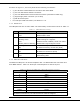
13 UPGRADING YOUR FIRMWARE The ViPR radio modem firmware is field-upgradeable using the unit’s Ethernet port. The process involves connecting to the IP address of the ViPR from a host PC and transferring firmware files via a Files Transfer Protocol (FTP) program. There are two sets of code in the ViPR Radio. The first set of code is the Modem Firmware and must be updated every time a software upgrade is needed. The revision number for the Modem Firmware is listed under the “REV” column in the table below.
1.5 4-3-2009 - Added TCP Proxy Feature - Added support for 900 MHz ViPR - Added support for ViPR Infrastructure Radio firmware update: ViPR-03_00-R - Added support for 900 MHz ViPR and for ViPR Infrastructure 1.6 6-9-2009 - Added Listen Before Talk Disable Feature Added RF MAC override Feature Added Periodic Reset Timer Bug fix related to Power PC lockup when resetting the DSP. 13.2 UPGRADE MODEM FIRMWARE PROCEDURE 1.
Figure 13.1 Use Windows Command Prompt to Telnet to ViPR Radio. 3. Enter in your username and password. 4. Type the following command then press enter: radio.upload.firmware.binary –v –f vipr_radio.bin You should see the following message in return: 100-Loading file "vipr_radio.bin"... 100-File imported successfully. 100-Entering flash programming mode... 100-Erasing flash... 100-Programming flash... 100-Restarting radio... 200-OK.
Figure 13.2 Using Windows Command Prompt to upgrade Radio Firmware. 5. Restart the ViPR. Tip: You can restart the ViPR by typing “stationreset” in the CLI then pressing enter. 13.4 VERIFY FILE INTEGRITY 1. Using your browser, connect to the unit’s IP address. 2. Enter the user name and password. Allow the Welcome page to load. 3. In the left pane, select UNIT STATUS. The Unit Identification and Status pane should display the newly upgraded firmware in its Banner and the H/W Status should also show Ok. 4.
– APPENDIX A – VIPR SPECIFICATIONS These specifications are typical and subject to change without notice.
RECEIVER RX Frequencies Data Sensitivity @ 10-6 Bit Error Rate (BER) (Maximum) Data Sensitivity @ 10-6 Bit Error Rate (BER) (Typical) Adjacent Channel Rejection Spurious Response Rejection Intermodulation Rejection TX to RX Time Channel Switching Time Receive Input Power MODEM/LOGIC Data Rate (Selectable) Modulation Type Addressing SETUP and COM Port Interface Data Rate Display 5 Tri-color status LEDs 001-5008-000 rev5_2.doc VHF UHF 136 - 174 MHz 406.125 – 470.000 MHz, 215 – 240 MHz 450.000 - 511.
Connectors Antenna Connector Serial Setup Port Serial Terminal Server Ethernet RJ-45 Power - I/O TNC female (Tx/Rx) DE-9F DE-9F 10 BaseT auto-MDIX Power Header DRL p/n 415-7108-113 (Weidmüller p/n 1615550000) 4 Pin, 3.5mm, Power Header Power Plug DRL p/n 897-5008-010 (Weidmüller p/n 1639260000) 4 Pin, 3.
– APPENDIX B – PRODUCT WARRANTY CalAmp warrants to the original purchaser for use ("Buyer") that data telemetry products manufactured by DRL ("Products") are free from defects in material and workmanship and will conform to DRL's published technical specifications for a period of, except as noted below, two (2) years from the date of shipment to Buyer.
– APPENDIX C – DEFINITIONS Access Point. Communication hub for users to connect to a LAN. Access Points are important for providing heightened wireless security and for extending the physical range of wireless service accessibility Firewall. A set of related programs located at a network gateway server that protects the resources of a network from users on other networks Airlink. Physical radio frequency connections used for communications between units Firmware.
acknowledgments. OIP makes the most use of the available bandwidth Static IP Address. A fixed address assigned to a computer or device connected to a network OTA (Over the Air). Standard for the transmission and reception of application-related information in a wireless communications system Static Routing. Forwarding data in a network via a fixed path PHY. A PHY chip (called PHYceiver) provides the interface to Ethernet transmission medium.
About CalAmp CalAmp is a leading provider of wireless communications products that enable anytime/anywhere access to critical information, data and entertainment content. With comprehensive capabilities ranging from product design and development through volume production, CalAmp delivers cost-effective high quality solutions to a broad array of customers and end markets. CalAmp is the leading supplier of Direct Broadcast Satellite (DBS) outdoor customer premise equipment to the U.S.