
User's Manual


GuardianManual001‐5006‐000Rev0 12|Page
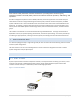
• GuardianradiomodemSETUPandCOMportsareDataCommunicationEquipment(DCE)devices
• Ingeneral,equipmentconnectedtotheGuardian’sSETUP/COMserialportisDataTerminalEquipment
(DTE)andastraight‐throughcableisrecommended.
Note:IfaDCEdeviceisconnectedtotheGuardianSETUP/
COMport,anullmodemcable/adapteris
required.
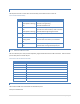
Thepin‐outfortheSETUPandCOMportsareshowninTable1.3.
Table1.3Pin‐outforDCESETUPandCOMport,9ContactDE‐9Connector
Contact EIA‐232FFunction SignalDirection
1 DCD
(1)
DTE←DCE
2 RXD DTE←DCE
3 TXD DTE→DCE
4 DTR DTE→DCE
5 GND DTE‐‐‐DCE
6 DSR
(2)
DTE←DCE
7 RTS
(1)
DTE→DCE
8 CTS
(1)
DTE←DCE
9 RING
(3)
DTE ‐‐‐ DCE
(1)Programmable.
(2)Alwaysasserted
(3)Forfutureuse
TheDCD,DTR,RTSandCTScontrollinesareprogrammable.Refertosection6.4forserialportcontrolline
configurations.
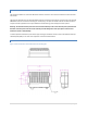
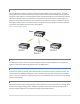
1.3.5 POWERCONNECTOR
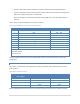
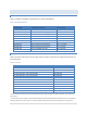
TheGuardianissuppliedwitharight‐anglepowerconnector(10‐30VDC).Table1.4showsthepin‐outofthe
powerconnector.
Table1.4Pin‐outofthepowerconnector
Contact#
(LefttoRight)
Color Description
4 FanPowerOutput(5V)
3 Black Ground
2 Red Positive(10‐30)VDC
1 White Enable
Note:TheWhiteEnablelinemustbetiedtotheredpositiveleadoftheconnectorfortheGuardiantofunction.