
User Manual

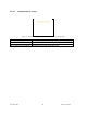
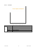
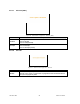
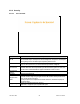
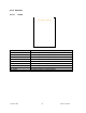
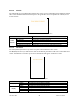
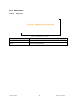
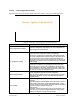
Table Of Contents
- 1.
- 1. Product Overview
- 2. Installation
- 3. Physical Description
- 4. Operation & Configuration
- 4.1 Browser-Based Setup and Status
- 4.2 LAN Setup
- 4.3 Login Screen
- 4.4 Interface
- 4.5 Setup Wizard (Bridge Mode)
- 4.6 Default IP Settings
- 4.7 IP Network Settings
- 4.8 Advanced IP Settings
- 5. Optimization & Troubleshooting
- 6. Specifications

120 40520-100a ViPR User Manual
58
4.8.5.2 AirLink
The Airlink RF layer (good/bad CRC) indicates how well it receives individual packets. Missing and bad
CRC counts should be minimized with respect to the good CRC count. To optimize the Airlink, refer to
section
5 below.
Figure 49 - Statistics – Airlink – Channel Utilization
Item Description
Pkts Delivered Total packets delivered over-the-air
Pkts Received Total packets received by over-the-air
Pkts with Good CRC Total packets received over-the-air with correct checksum
Pkts with Bad CRC Total packets received over-the-air with incorrect checksum
Airlink
statistics
Pkts with missing fragments Total packets received over-the-air with missing fragments
4.8.5.3 Interfaces
The LAN (Ethernet) Interface layer shows reception and transmission traffic counts.
The RF(OIP) interface layer indicates the result of the RF link performance. RF errors result in RX Error
counts. Transmission errors show up as retries and timeouts and appear as TX Error counts.
Figure 50 - Statistics – Interfaces
Item Description
RX Pkts Total packets received by Ethernet interface
LAN(LAN)
TX Pkts Total packets sent by Ethernet interface
RX Pkts Total packets received by RF (OIP) interface
RX Error Total packets received by RF (OIP) interface with errors
TX Pkts Total packets transmitted by RF (OIP) interface
RF(OIP)
TX Error Total packets transmitted by RF (OIP) interface with errors