
User Manual

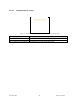
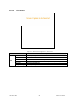
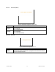
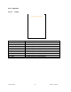
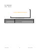
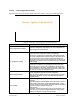
Table Of Contents
- 1.
- 1. Product Overview
- 2. Installation
- 3. Physical Description
- 4. Operation & Configuration
- 4.1 Browser-Based Setup and Status
- 4.2 LAN Setup
- 4.3 Login Screen
- 4.4 Interface
- 4.5 Setup Wizard (Bridge Mode)
- 4.6 Default IP Settings
- 4.7 IP Network Settings
- 4.8 Advanced IP Settings
- 5. Optimization & Troubleshooting
- 6. Specifications

120 40520-100a ViPR User Manual
51
The following setup example would allow the “Sender” unit to communicate with different multicast
groups. The settings shown in
Figure 40 below, and also represented in Figure 41, would enable the
Sender unit to reach all entities of the various groups. Setup is done on the Base side.
Figure 40 - Multicast Window Details (On the Main ViPR unit)
Multicast (Enabled/Disabled)
Enables or disables the registration of the multicast groups by the main ViPR
unit.
Outbound unit address Indicates the “All Remote ViPR unit” multicast group
Multicast Address List Indicates the various “Remote Host” groups
Figure 41 - Registration to multicast group
Sender
Network
“All Remote ViPR”
group
(224.168.201.1)
Master ViPR unit
RF Airlinks
Remote Host
Remote Host
Remote Host Remote Host Remote Host
“Remote Host” group 1
(224.168.200.1)
“Remote Host” group 2
(224.168.200.2)
Remote 1 Remote 2 Remote 3
Remote 4
Remote 5