
User Manual
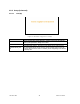
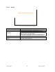
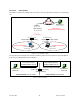
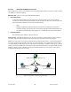
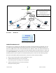
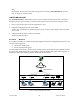
Table Of Contents
- 1.
- 1. Product Overview
- 2. Installation
- 3. Physical Description
- 4. Operation & Configuration
- 4.1 Browser-Based Setup and Status
- 4.2 LAN Setup
- 4.3 Login Screen
- 4.4 Interface
- 4.5 Setup Wizard (Bridge Mode)
- 4.6 Default IP Settings
- 4.7 IP Network Settings
- 4.8 Advanced IP Settings
- 5. Optimization & Troubleshooting
- 6. Specifications

120 40520-100a ViPR User Manual
49
Figure 37 - Reception of multicast packets (Second step)
4.8.3.4.1.1 Broadcast
Figure 38 - Broadcast Window Detail
DIRECTED BROADCAST
Each interface of a unit has its own IP address and netmask. From the IP address and netmask, it is easy
to calculate the broadcast address associated to the interface. For instance, if the Ethernet interface ad-
dress of an ViPR unit is 172.30.1.1/24 and the RF interface address is 10.0.1.2/24, then the broadcast ad-
dress of the Ethernet interface is 172.30.1.255 and the broadcast address of the RF interface is 10.0.1.255.
The “Directed Broadcast” radio buttons let the user select whether the unit must forward or not directed
broadcast packets. Upon reception of a directed broadcast packet, the unit takes the following actions:
If the directed broadcast address match with one of the unit’s interface broadcast address:
• Keep a copy for itself (pass to internal applications, if any).
• If directed broadcast packets can be forwarded:
Forwards the packet according to the routing table.
• If directed broadcast packets cannot be forwarded:
Silently discards the packet.
Sender (owner of multicast group 226.1.2.3)
Receiver 1
(member of 226.1.2.3)
Receiver 2
(member of 226.1.2.3)
Receiver 3
(member of 226.1.2.3)
Internet
IP Router
IP Router
IP Router
IP Router
Paths from Sender to Members (Receiv-
ers 1, 2, and 3) flow in the Internet from IP
Router to IP Router to reach
Destinations 226.1.2.3.
Paths are not forwarded over interfaces
that do not lead to a multicast group
b
5
1
2
2
3
3
4
Receiver
(not a member of 226.1.2.3)
Receiver
(not a member of 226.1.2.3)