
User Manual
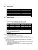
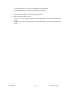
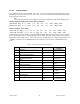

Table Of Contents
- 1.
- 1. Product Overview
- 2. Installation
- 3. Physical Description
- 4. Operation & Configuration
- 4.1 Browser-Based Setup and Status
- 4.2 LAN Setup
- 4.3 Login Screen
- 4.4 Interface
- 4.5 Setup Wizard (Bridge Mode)
- 4.6 Default IP Settings
- 4.7 IP Network Settings
- 4.8 Advanced IP Settings
- 5. Optimization & Troubleshooting
- 6. Specifications

120 40520-100a ViPR User Manual
25
3.2.2.1 Output Samples
From command window, type telnet nnn.nnn.nnn.nnn 6272 and the unit’s diagnostic output
will display on screen (where nnn.nnn.nnn.nnn is your unit’s address in dot decimal format) (Thin-
ning value must not be zero).
Note:
No overhead is generated in the ViPR unit if no online diagnostic connection is actually made.
Sample output for bridge mode (no IP address available)
[00:00:03:09], 0, 9, 100, 1, 5, 38, -51, -70, -108, 1000, 200
[00:00:03:09], 0, 9, 100, 1, 5, 38, -51, -70, -111, 1000, 200
Sample output for router mode
[192.168.36.188], 0, 9, 10, 0, 127, 46, -42, -70, -107, 1000, 200
[192.168.36.204], 0, 9, 10, 0, 103, 42, -53, -70, -110, 1000, 200
Decoding the last line (see
Table 7): unit is 192.168.36.204 IP address (in router mode), type of report is
0, there are 9 fields to follow, 1/10 sampled packets are output, DC input is used, Volts are 10.3, Internal
temperature is 42°C, PER of 10
-5.3
, with a carrier level of -70 dBm signal, an average background level of
-110dBm, a forward power of 1000 milliwatts (1.0 watt), and a reverse power of 200 milliwatts (0.2
watt).
Table 7 – Decoding Sample Output for Router Mode
Field # Field Name Sample Output Sample Output
Decoded
1 IP address
[192.168.36.188]
Unit’s IP address is
192.168.36.204
2 Report Type
0
0
3 Number of Fields to Follow
9
9
4 Number of data packets before a diagnos-
tic message is delivered
10
1/10 sampled pack-
ets are output
5 Flags
0
DC input
6 Voltage Level
103
10.3 V
7 Internal Temperature
42
42°C
8 PER
-53
10
-5.3
9 Signal RSSI
-70
-70 dBm
10 Background RSSI
-110
-110 dBm
11 Forward power
1000
1000 mW (1.0 Watt)
12 Reverse power
200
200 mW (0.2 Watt)